In 2010, me having already exploited the DY86, a Czech experimenter nicknamed “DANYK” came up with an oddball Soviet vacuum stabilisator tetrode “6VS-1”, which produced copious amounts of X-rays in hot-cathode mode. He got pretty good radiographs, nevertheless. So, I have got an inspiration and obtained a few:
 2.50€/piece from a Bulgarian stockpile…
A specialty in these tubes is their construction. During normal mode of operation (high voltage stabilisation at a few hundred microamps max), a visible electron beam with a small diameter is focused on the thin anode plate. When overdriven at 30-40 kilovolts for a short period of time, X-rays with a sufficiently enough energy to pass through the glass are created.
6VS-1 at 35 kilovolts, observe the electron beam and Geiger counter sound.
I have built numerous high voltage supplies for these tubes back in the day. Here’s one of the prototypes, a multiplier-based 40 kilovolt supply with cathode current and frequency regulation:
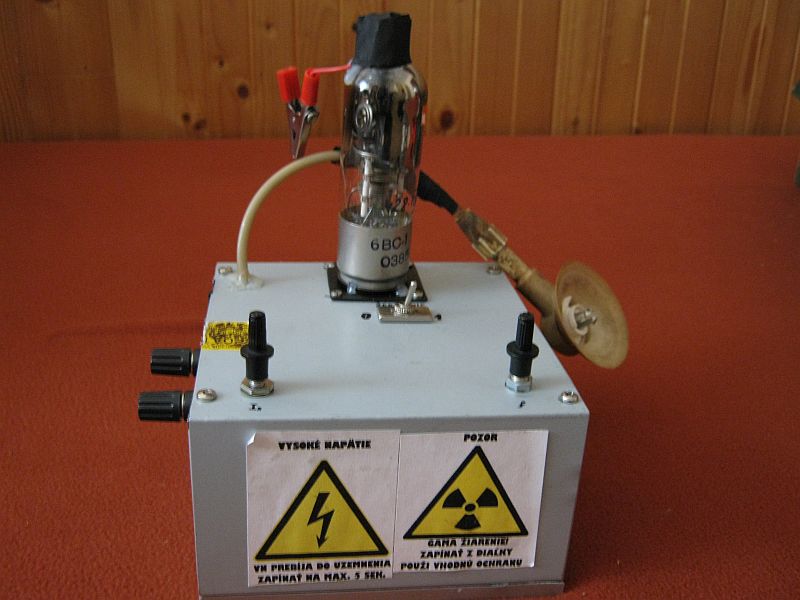 The suction cup had a high voltage resistor, in order
not to fry the 4-stage multiplier with inrush current.
And it sure did a mayhem when it ran – of course, controlled remotely:


In a head-to-head comparison with the DY86 ran in cold cathode, this is a more powerful X-ray emitter. Here’s a 4 second exposure near the tube where you can see energized particles (photons) hitting the CCD sensor, resulting in colorful “dots” in the picture:
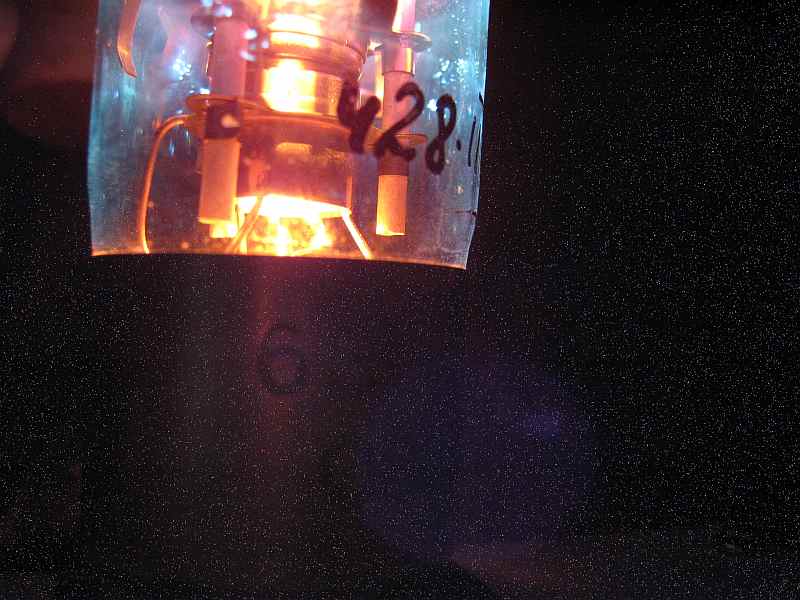 Maximize to see the artifacts
And now an attempt to radiography. As mentioned in the DY86 article I did not want to mess with a photosensitive paper and developing it afterwards in a dark room, so I have attempted the “fluoroscopy” method again. I used some fluorescent foil strips, from an “emergency-exit” glow in the dark sign, and some blue-emitting, calcium tungstate (scheelite) “PERLUX” intensifier screens, from the former GDR…
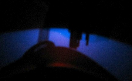 Enough for the screen to make a blu-ish shine..
 … but not enough radiation to radiograph this way.
“DANYK” had been more lucky in this case.
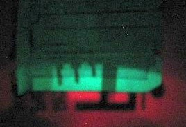
This was the best output I have got with a setup described above. Maybe if I had been shining through a photosensitive paper for 30 seconds or so, the result would have been vastly improved – but that did not occur, as I have moved to real x-ray tubes shortly after this. 🙂
What do you think about running this tube on an AC flyback?
I have already tried to run it on a Tesla coil for a few seconds and it emits X-rays in cold cathode mode too.
I tried various peak voltages between 25-45kV.
https://www.youtube.com/watch?v=_adcy3wkWO8
Here’s my Tesla coil running on 1.2kV from a microwave transformer current limited with a 40 Watt fluorescent lamp inductor.With this setup,I was able to make 25kV peak voltage at best(spark about 25mm).
I replaced the MOT with a 7kV 50mA neon sign transformer and I can now make 45kV,but soon will make another Tesla coil for 50kV and more.
Danyk has been able to make a lot of x-rays from a sodium lamp with evacuated outer bulb on a Tesla coil.
Most of the AC flybacks I had at the time were designed to run in conjunction with a half-wave multiplier (the 8 kV ones), or were DY86 rectified (20 kV). Anything above that, and the flybacks arced over internally.
Note that the “1mm ~~ 1kV” assumption usually only applies to DC and spherical electrodes, with “standard” humidity and pressure, and can be used as a gross guesstimate up to some 15 or 20 kilovolts only. /A 70kV DC supply can strike in-between a 14 cm distance, give or take./
DANYK made a Geiger counter go ticking away with a sodium discharge lamp placed on a Tesla coil, but that won’t be enough for making (sensible) radiographs…
If you connect 50kV to this tube,will it arc over inside or outside?Does it also work in cold cathode mode or reverse polarity?
At approx. 45kV and over, the anode cap will start arcing to the base, i.e. where the glass meets the metal. An internal arcover will occur over 55 kilovolts in forward direction, and it will destroy the tube.
In reverse direction, the high voltage will immediately strike to the heater/cathode – I have not tested the tube in cold cathode, owing to the internal construction of the tube I don’t think it has much potential that way.
My experiments also showed that an HV pulse can work well.
At least with more delicate tubes like the DAC32 and 5642 that fail in minutes with continuous HV don’t seem to be affected by pulses.
Used a gas igniter that worked from 9V DC, the lower voltage sort don’t seem to work though someone found that the old “zapper” style gas lighters work if the output capacitor is upgraded as its secondary is vacuum potted.
The old method of putting two secondaries in series with a single capacitor and HV resistor from centre to ground works, but you only get at most a 40% increase in peak voltage.
I have acquired a 6VS-1 tube and I am seeking advice on how to run this device to emit soft x-rays on a continuous bases for R&D project. I look forward to hearing from you.
Regards
Eamon
The electron beam will eventually “drill” a hole in the anode if ran continuously.
To try this setup out, limit the maximum voltage on g2 to approx. 300V IIRC, e.g. with a stack of glow lamps, g1 is connected to ground and set cathode current e.g. with a potentiometer between cathode and ground. Use a microammeter to measure it.
The tube will withstand up to 0.4mA at 35-40kV for a few seconds. For continuous run you ought to stay below 100uA though.
Needless to say, a proper x-ray tube would do better. Please remember that this was just an experiment.