This article describes three different ways on how to cope with the digital-level RGB videosignal, often found in various computing equipment of the 1980s and early 1990s, so that it can be connected to other display equipment, besides vintage monitors: be it Commodore 128 or Amiga, IBM MDA/CGA/EGA, certain clones of the ZX Spectrum, arcade machines, and so on.
 A TTL-to-composite converter for MDA and CGA (schematic below)
Originally, this digital interface provided a maximum of sixteen colors from one palette (4-bit RGB). That is, eight basic colors of “low intensity”; black, white, red, green, blue, yellow (red+green), magenta (red+blue) and cyan (green+blue). Plus another eight to get the “high intensity”, or lighter versions, of these basic colors, yielding sixteen in total. Later, this limit was surpassed by switching the palettes and/or varying the Intensity for four levels, instead of two (low and high intensity), to a maximum of 64 colors.
On a monochrome display, like the IBM MDA or Hercules, three – and sometimes four – shades, could be used to display text or graphics. Depending on the monochrome monitor used, this was either green, amber or gray: video line low (black), video line high (green/amber/gray) and video line high with high-intensity line high (light green/amber/gray). The fourth shade, which was not always supported, was setting the video line low with high intensity line high, yielding dark green/amber/gray, depending on the phosphor.
Now, there are at least 3 different ways on how to get these video modes working with “more modern” displays:
- Option 1: Bringing the signal levels down, mixing Intensity and upscaling
This technique involves bringing the 5-volt TTL RGB signal levels down to 0.7 volts, as used with analog RGB (e.g. in VGA). Then, the Intensity signal is mixed in, both passively and with a diode-clamp/pull-up circuit. Connecting this to a suitable HDMI or VGA upscaler, to “scale up” the resolution, yields a video signal that is compatible with more modern displays and does not require a vintage monitor, which relies on the slower horizontal sync frequencies (“newer” monitors don’t go that low on HSYNC).
On display devices that accept an analog RGB input directly (TVs with a SCART/Euro-AV connector), the upscaler can be omitted, but only if the input video signal is conformant with the PAL (15.625kHz HSYNC, -50Hz VSYNC) or CGA/NTSC standard (15.75kHz HSYNC, +60Hz VSYNC), and the TV supports it.
However, note that you might need to force the TV to use the SCART RGB video input by applying +1V to +3V onto pin 16, or find a setting in the Menu to do it for you.
Also note that the current draw from pin 16 may reach up to 40 mA!
The following schematic, inspired by H2Obsession, was used by me together with a TV with a SCART RGB input, and also with a Gonbes GBS-8220 VGA upscaler, on multiple TTL RGB devices:
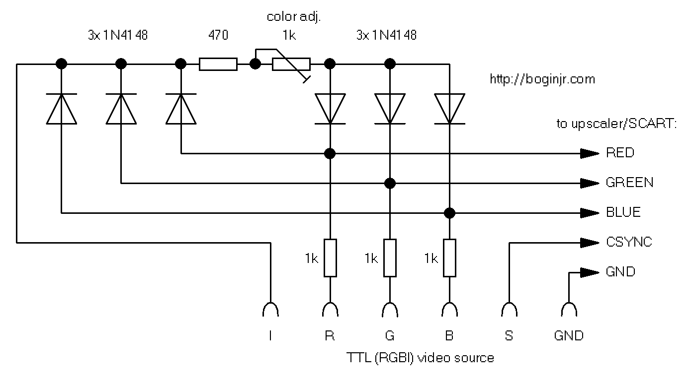 By the way, connecting the “Intensity” pin is fully optional, the circuit also works with RGB TTL video sources that do not make use of it. If you do use it however, be sure to calibrate the colors with the “color adjust” trimpot, preferably by generating a 16-color test pattern, first.
 Slovak ZX Spectrum clone “Didaktik M”, with a hacked-in RGB/S connector.
These signals were taken straight from the Russian PLA (“ULA”) – Angstrem Т34ВГ1 (КА1515ХМ1).
Here’s an example – a Slovak ZX Spectrum clone “Didaktik M”, compared with its internal composite video out (on the left). This was connected directly from the circuit above, to the SCART connector of the TV, without an upscaler. Notice the much better contrast and a lack of “ghosting” – which is very prominent on the composite video.
 Composite video on the left; RGB from the circuit on the right.
The only real limitation here is the upscaler that you use, or if you use the RGB input on a TV directly, the signal must conform to the PAL or NTSC standards (and the TV must support an analog signal).
As an example, the GBS-8220 will not sync on an MDA/Hercules signal (18.43kHz HSYNC, -50Hz VSYNC), or the 640×400 “Hi-Res CGA” from an Earthstation-I. Also, the upscaler provides both HSYNC/VSYNC and CSYNC (composite sync) inputs; however, the HSYNC/VSYNC combo is only used when a VGA signal is being fed.
Thus I had to combine the HSYNC/VSYNC from a CGA card, into single composite sync CSYNC, otherwise it would not work at all. And this ought to be done properly with a sync combiner IC, but there’s also a sloppy way of doing this: using a quad-XOR gate (see schematic below), that can work just as well.
 RGB out from a CGA into the GBS-8220 upscaler.
HSYNC+VSYNC combined into CSYNC with a XOR gate.
- Option 2: TTL-to-monochrome composite video
This approach was used with my PMD-60.1 monochrome monitor – which is basically a portable TV, but with a green screen, and without a channel tuner, MF separator and a sound stage – it only had a composite video input, designed for PAL (15.625kHz HSYNC, -50Hz VSYNC). The circuit is a small variation from the one above:
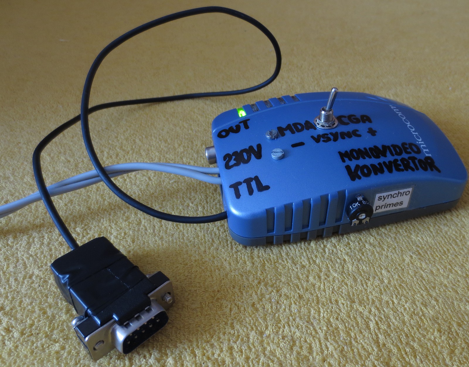
 CGA/MDA TTL-to-monochrome converter (the “blue box” above)
This circuit already has the makeshift “sync combiner” present, combining HSYNC and VSYNC into CSYNC + accounting for positive or negative vertical sync pulses (into the last XOR gate: logical 1 for CGA, logical 0 for MDA/Hercules).
Also, the “Intensity” input is being handled, to account for three different shades: black/no video, normal text, high intensity text. All of these TTL levels are smacked down and mixed passively to one single composite video signal with sync. This is, of course, miles away from resembling a video signal conformant to the standards, but it usually does work (if you fiddle with the sync adjustment trimpot, until the image stops dancing around).
On a CGA input video signal, the Green video line is used as a compromise. Everything purely red or blue may end up not showing properly.
 Composite MDA video (18.43kHz), with high intensity support, on a PMD 60.1 TV with its horizontal stage tweaked
Of course, even here, the display device (or TV) must be able to sync up to the video signal. With a mono CGA, it’s enough for the TV just to support NTSC. Or if not, you can stabilize the jumping picture by tweaking the vertical stage frequency, until it is stationary. But with an MDA or Hercules, 99.9 % of TVs won’t sync to those frequencies, resulting in a corrupted or a blank picture.
With a TV that has a free-running analog horizontal sweep generator, you could – technically – tweak its frequency to lock on something around 18 kilohertz. However, this can strain the horizontal output transistor (HOT), or the flyback transformer, and can lead to damage.
In my case, the green screen PMD 60.1 employs a TBA950 in its horizontal sweep stage. Trimpots in the back of the modules can be then used to modify the frequency between 14 to 18 kHz, and the phase. Running the flyback on 18 kilohertz actually decreased the high voltage output, and the length of the flyback pulse, so the picture was narrower and visibly squished. This was corrected by replacing the capacitor parallel to the HOT, and also using a different capacity for the CRT curvature (S-correction) capacitor, in series with the deflection coils.
The vertical stage was also accustomed to fit the size of the MDA video.
 Composite CGA video (monochrome, using the green video line), running Windows 1.01.
The moiré (oval lines) are created by the camera
- Option 3: TTL-to-color composite video
And this is where things start getting messy. Not only the color video quality will be degraded (check out the “Didaktik M” example above), and suspect to various artifacts, there’s also no easy way of doing this without a dedicated IC. Also, the use case is to convert an already conformant PAL or NTSC RGB signal into a PAL or NTSC-conformant composite video signal – most converter ICs won’t make composite video out of some funky high-resolution TTL modes. So if you already have an upscaler, or an RGB signal conformant with PAL/NTSC and a TV or monitor to display it on, forget this step.
If you do want to pursue this approach though, check out the datasheets and recommended operating circuits for either the Texas Instruments LM1886/LM1889 combo (the first to convert the RGB into Y, B-Y and R-Y signals, the second to form a video signal), or for the Motorola MC1377 RGB to PAL/NTSC converter.
I have an RCA Lyceum tv that supports both rgbi and rgb analog but the problem is its only 8 colors so when I got picture, it looks like crap. Would you know how to raise it up to 16 colors? Any way to mod it from inside?
If it already supports TTL RGBI (RGB with “intensity”) then there already should be a way for sixteen color support. As in, you have black (no color), white (red+green+blue), red, green, blue, yellow (red+green), magenta (red+blue), and cyan (green+blue); which is eight colors in total. Plus, with the intensity pin high, that’s gray, bright white, bright red, etc – another eight colors, so sixteen in total. Check your connections perhaps; probe the Intensity/Brightness pin with a scope to check.
Or, try the first schematic – bring the TTL RGBI signals down to analog levels and use the trimpot to mix in the “high intensity” so you get analog RGB – without caring for the Intensity/Brightness pin.
If both don’t work, you might want to consult an old timer repairman, to rule out issues with your TV’s video input. I do not have experience with TV sets from over the pond, sadly.
Hello, I sincerely congratulate you on your achievement in electronics. I would like to ask you if there is an adapter that allows you to pass from monochrome composite video to an mda / hercules monitor. I have an old amber phosphor monitor with that input and I don’t have a computer to use it so I wanted to be able to feed it. Best regards and many thanks in advance.
What is your monochrome composite video source?
If the monitor only has TTL inputs, you need a sync separator circuit, such as with an LM1881 to get VSYNC and a XOR with CSYNC to get HSYNC. Be warned that if the video signal is not 18,43kHz to drive the MDA monitor, and if the monitor is not designed for multi-sync, you can damage the horizontal stage.
Hi thanks, I want to connect the monochrome output of an apple iic to a Commodore 75bm13 monitor which is mda/hercules compatible and only has a 6 pin input. Kind regards!
Short answer: not possible.
Long answer: not possible without modifying both the horizontal and vertical stages of your monitor. http://boginjr.com/electronics/old/tesla-pmd60/
Hi, thanks again, look, I found an interesting article from 1989 in a magazine called Elektor, it talks about an “easy to build” adapter but I’m not so sure about that. Do you know the faith of someone who has done a circuit like this? I attach the link of the article in Google Drive. Kind regards
https://drive.google.com/file/d/1LXFILuZbydhwJqnjTMeioxBP31Mp1-_v/view?usp=drivesdk
The circuit just splits the composite signal into video, HSYNC and VSYNC (as I mentioned you could do a similar operation with an LM1881 and a XOR gate), but connecting a 15,625/15,75kHz synchronization signal (PAL/NTSC) from the video output of a home computer into a 18,43kHz MDA monitor is something I do not find a good idea. But you can try.
Hola, sinceramente te felicito por tu logro en electrónica. Me gustaría consultarte si existe algun adaptador que permita pasar desde video compuesto monócromo a un monitor mda / hércules. Tengo un viejo monitor de fósforo ámbar con esa entrada y no tengo una computadora para poder usarlo, entonces quería poder ingresarle señal. Saludos cordiales y muchas gracias de antemano.
………
Hello, I sincerely congratulate you on your achievement in electronics. I would like to ask you if there is an adapter that allows you to pass from monochrome composite video to an mda / hercules monitor. I have an old amber phosphor monitor with that input and I don’t have a computer to use it so I wanted to be able to feed it. Best regards and many thanks in advance.
Pour un oscilloscope des années 1980
utilisant en interne d’un moniteur monochrome vert,
avec les entrées HSYNC – VSYNC – Vidéo – Intensity
Je recherchai depuis longtemps une solution pour l’équiper
d’une sortie externe vers un écran moderne (vidéo ou VGA)
de plus grande taille pour plus de confort de lecture.
Maitrisant bien l’électronique en général mais peu dans le domaine vidéo,
Plusieurs essais même avec des moniteurs d’époque MDA Hercules
ont été in infructueux.
Vos explications précises me semblent interessantes pour poursuivre mes essais.
Merci de tout ces détails sur cette technologie vidéo ancienne.
Bernard Renouil (France)
————————————-
For an oscilloscope from the 1980
internally using a green monochrome monitor,
with the inputs HSYNC – VSYNC – Video – Intensity
I have been looking for a long time for a solution to equip it
from an external output to a modern screen (video or VGA)
larger in size for more reading comfort.
Having a good command of electronics in general but little in the field of video,
Several tests even with vintage MDA Hercules monitors
were unsuccessful.
Your precise explanations seem interesting to me to continue my tests.
Thank you for all these details on this ancient video technology.
Bernard Renouil (France)
What kind of oscilloscope is it? You might find the required clock rates, required for the external monitor (I presume you’ve meant video output instead of input) somewhere in the technical docs.
Or, try a vintage NEC MultiSync CRT, these ones could sync on to a horizontal frequency range between 15 to 31 kHz freely, i.e. instead of arbitrary resolutions.