To go along with flyback drivers, X-rays and other high voltage stuff, I have decided to build myself a Tesla coil. Because I live in an apartment building though, there would be no place to accommodate and run monstrous coil designs, not mentioning interference, so that is the reason why I’ve opted for small and sweet portable setups like this one is. Behold!
 In classic mode of operation (3.5cm sparks)
I had been in a dilemma in which topology should I’ve went for. Nikola Tesla’s original creation – the spark gap Tesla coil – has its advantages at high input powers; transistorized (solid-state) Tesla coils need a good driving circuit and are more prone to failure, but since at the time I had been making this coil one of my sources for obtaining electronic parts were black and white tube television sets; I have chosen the vacuum tube (VTTC) design, as vacuum tubes are mostly foolproof and sturdy at high voltages and don’t need special driver circuits.
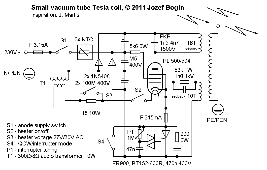 Schematic, click to enlarge
The basis for almost every VTTC is a class C-Hartley oscillator. Here, the anode supply is obtained from mains through a multiplier wired in a bit non-standard way, to increase peak-to-peak voltage. At this power output, the resonant capacitor is nothing unusual; a parallel connection of a few nice foil ones rated 0n5 is going to do the trick. To increase efficiency and decrease input current draw, there’s a thyristor (SCR)-based interrupter (staccato) circuit, which – when properly tuned – gives sword-like streamers double in length (7 cm) !
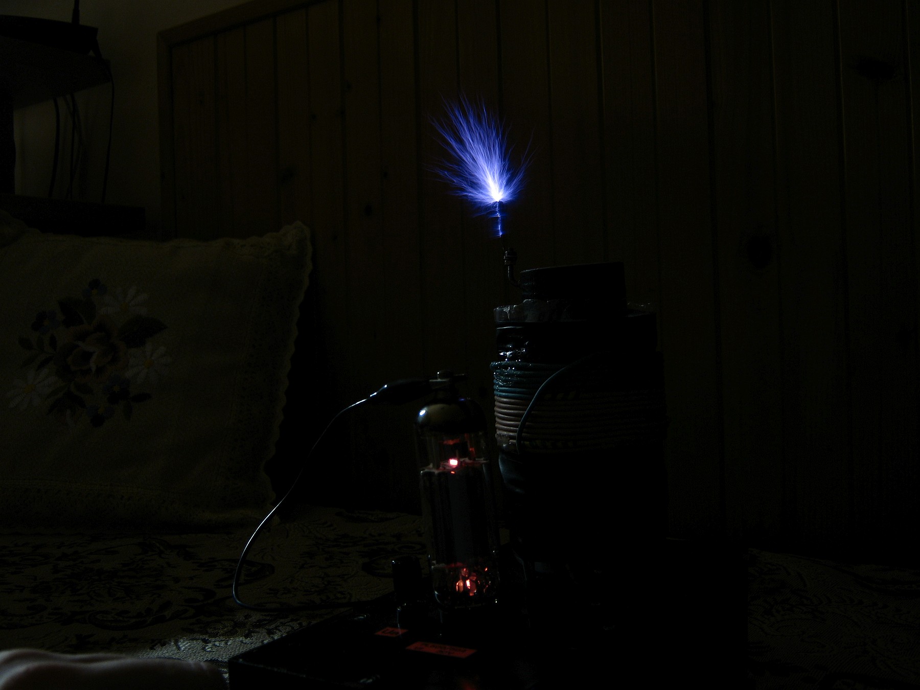 Interrupter mode (staccato), 7cm sparks
The tube which is used in my setup comes from a horizontal deflection circuitry of a B&W television set. I’m using a PL500 made by RFT, but with any similar pentode tubes like PL36 (EL36), PL504 you’re good to go. These were extensively used in every European black and white televisions through the 60s-70s.
However if you happen to have a PL509, EL509 or its Soviet equivalent 6P45S, it is easy to get 20 cm streamers with a microwave oven transformer supply and a good resonant cap.
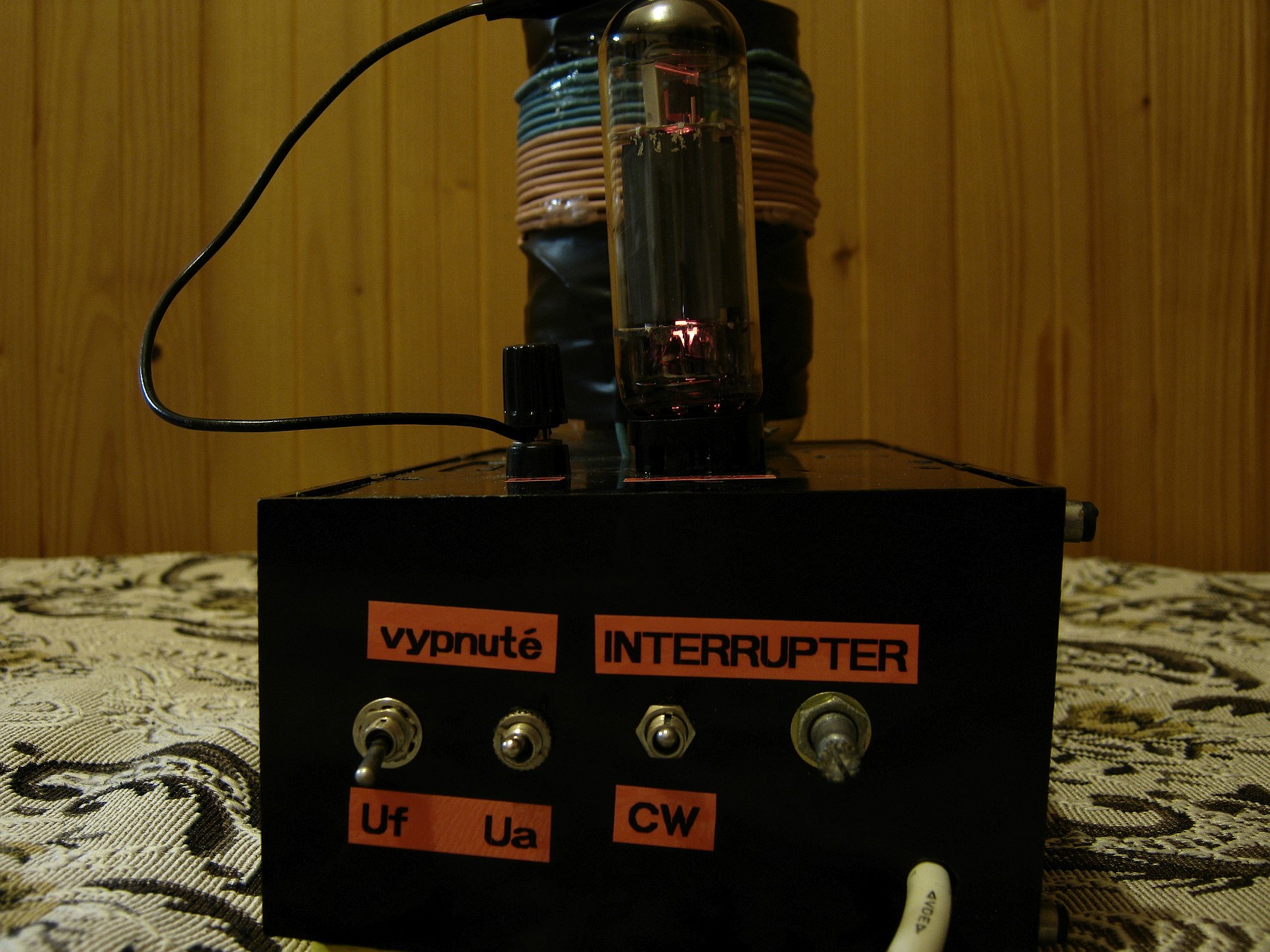 Control panel
And, when properly tuned, the anode doesn’t go red even after 4 minutes of continuous run. So a nifty table decoration I’ve got here! 🙂
You might have noticed a fuse in the cathode connection, as presented in the above schematic. Well, this circuit has some unfortunate consequences with some PL504s: when mistuned (too little or too many feedback turns), sometimes the circuit abruptly stops oscillating and grabs a huge inrush current which ruptures the thin internal cathode connection, rendering the tube useless.
To prevent this (if this would ever happen to you), install a 300-400 mA fast fuse in series with your cathode. After this happens, you need to tinker with the number of primary/feedback turns, usually adding more feedback turns solves the situation.
Now for some videos!
In operation
A lightbulb on break-out point
Hi Bogin,
A month or more ago, I asked you a question about NTC resistors and I did not get an answer to this question, I hope that the reasons for this are not serious (illness or the like). I resolved the problem with NTC resistors with the help of experienced friends. I hope that and you will be able to answer the following two questions:
1. In the scheme you indicated that the secondary spool has sixteen threads, and only ten can be seen in the photo. You also specified the number of feedback threads in the scheme, and only six are visible on the photo. I am convinced that the threads are jammed only in the yen layer. What is the correct .
2. You have indicated that you have four switches, and only three of them are visible in the photo. Which one did you have? You might have connected the PL504 directly to the 15 ohm threshold, and installed the switch only to bridle the resistor. I hope you will my question is to find a living and a hell. Sorry for my bad English language Thank you!
Hi Bogin!What is the value of the NTC resistor, individually
Ahoj,
tiež mám problém s prerušovačom. S PL504 ten prerušovač pracuje perfektne, ale keď nahradím PL504 elektrónkou 6P45S http://www.russiantubes.com/prop.php?t=12&p=276 prerušovač nepracuje – nijako sa na výbojoch neprejavuje (ako keby bol spínač S4 zopnutý) – ani pri ladení potenciometrom P1.
Vedel by si mi prosím poradiť ako upraviť prerušovač aby pracoval so 6P45S?
ďakujem,
Question, how small can a visually functional vacuum unit be, im trying to create a visual representation of electricity for a Element feature at a wedding.
Please advise, thank you
This particular one is a “desktop” version. There are even smaller builds, but the spark lengths are small fractions of the secondary coil heights… depends on the tube, anode voltage and LC tank circuit tuning – whether it is close to resonance.
With high voltage circuitry… don’t turn your wedding into a funeral 😉
Hi, Can anyone tell my how many turns have secondary winding?
This particular one had a ~10cm tall secondary with a diameter of 5cm, the wire gauge had been 0.09mm, so there were approx. 1100 turns.
If you have any more tesla circuit post them please
I would love it if you would put the measurement’s of your Coil s Length, diameter,r and wire size .It looks like fun. I guess a 6lq6 with correct pin wiring to duplicate the tube you show could work .Thanks
I’m not sure of the rating of the capacitors in the multiplier circuit? M5 400v?
Also the 2x 100M 400V caps?
Thanks.
Hey Rob,
M5 = .5uF = 500n or 470n, the same convention for 100M (100uF).
Regards
i have a mullard qv06-20 tube i would like to use – what modifications to the circuit are required ?
do i need to add more windings to the coil if i want it to use with a flyback
or should i just try it?
This lad experimented with such a design, but it was a more powerful tube (PL/EL509 or GU50). Try asking him.
can this be used to drive a flyback transformer?
Yes.
Hi Jozef,
Thanks for your last comment in which you mentioned the screen grid. I made a final check on the wiring and discovered that I connected the screen grid to the anode supply point. Now I rewired it to the position as indicated in the schematic. It works. Thanks very much for the help!
John
Hi Jozef,
Yes, I wired the multiplier circuit according to the schematic, and am getting about 700VDC at the anode. Strong streamers from the break-out point of the secondary. The VTTC now works in a CW mode. However, when I switch it to the interrupter mode there was no interruption at all and the VTTC still works in the CW mode. I did try your suggestion but without success. I noticed that once the SCR is on, it remains on until the switch at the cathode circuit is momentary switched on and off. I cannot figure how this interrupter circuit works.
John
Hm.. There’s one more thing to do: try putting a diode with the anode on your SCR’s anode and cathode to G2 of the tube. Beats me if this won’t solve your problem.
Hi Bogin,
Thanks for the VTTC schematic. Can you please explain how the interrupter circuit works. My impression is that in a DC circuit, once the SCR is fired it remains on untill the cathod and anode voltage falls below holding value. I built the VTTC it works in CW mode and not in interruption mode. Please help. Thanks.
John
Check whether you have the multiplier wired like on the schematic. It is quite non-standard, increasing “voltage swing” on the anode.
If it doesn’t help, try fiddling with the number of feedback turns. Or, try a 100-220 ohm 2W resistor across K-G of your thyristor.