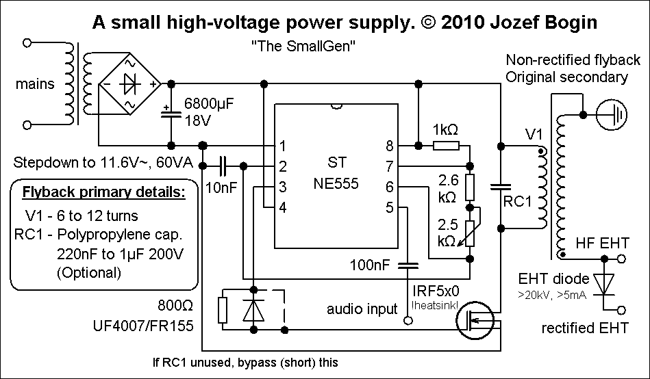
This single transistor flyback driver topology was created in response to achieve higher efficiency and higher output voltages from ordinary CRT television flybacks (diode split flybacks), for experiments such as x-rays or ionic lifters, without having to make any external HV multipliers. Since these flybacks are normally sealed in epoxy and can withstand an output voltage of 50 to 75 kilovolts, why not use them in drivers such as this one… 🙂 Moreover, the simplicity of this circuit also adds a possibility of some simple audio modulation of the arc. So, let’s begin!
 The quasi-resonant topology
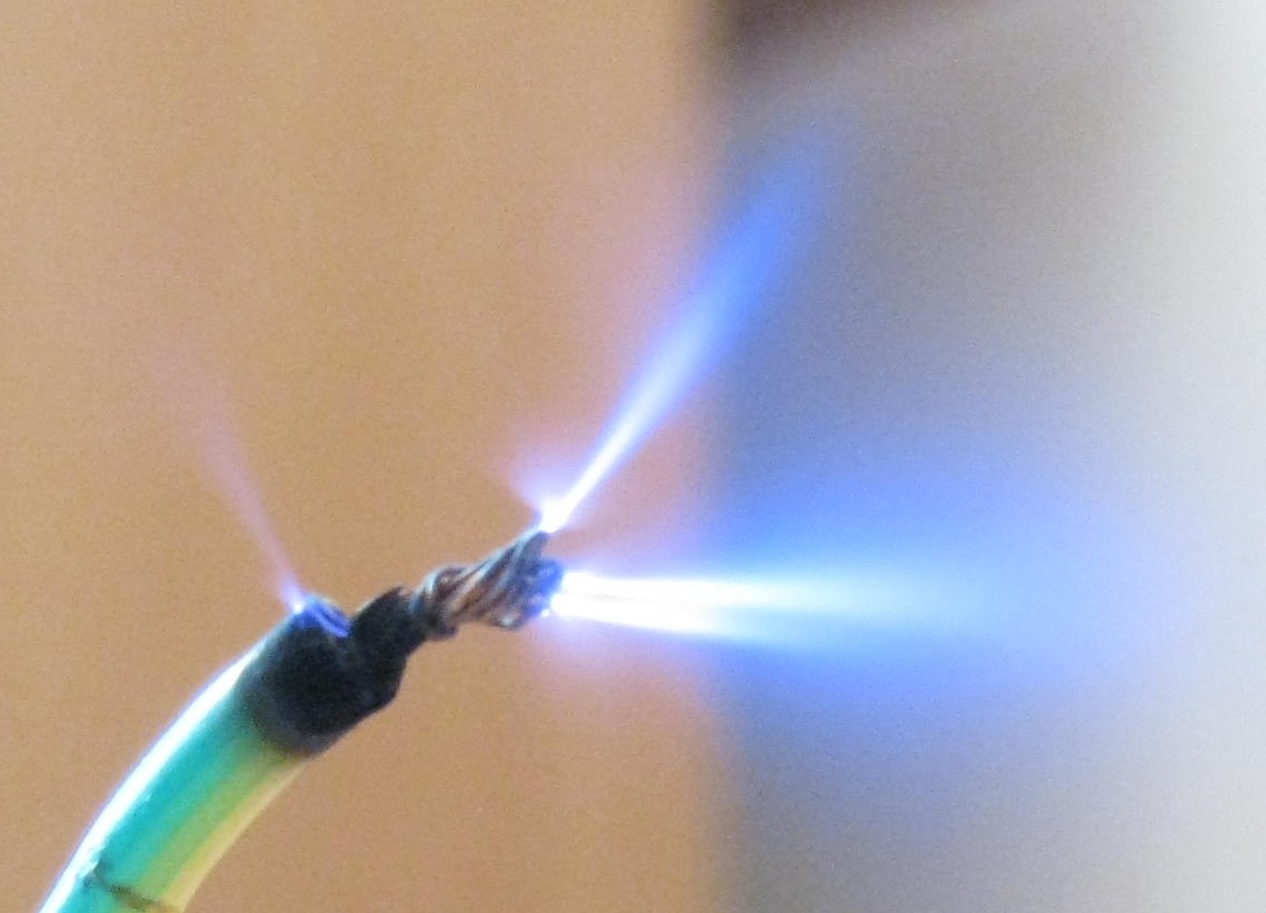
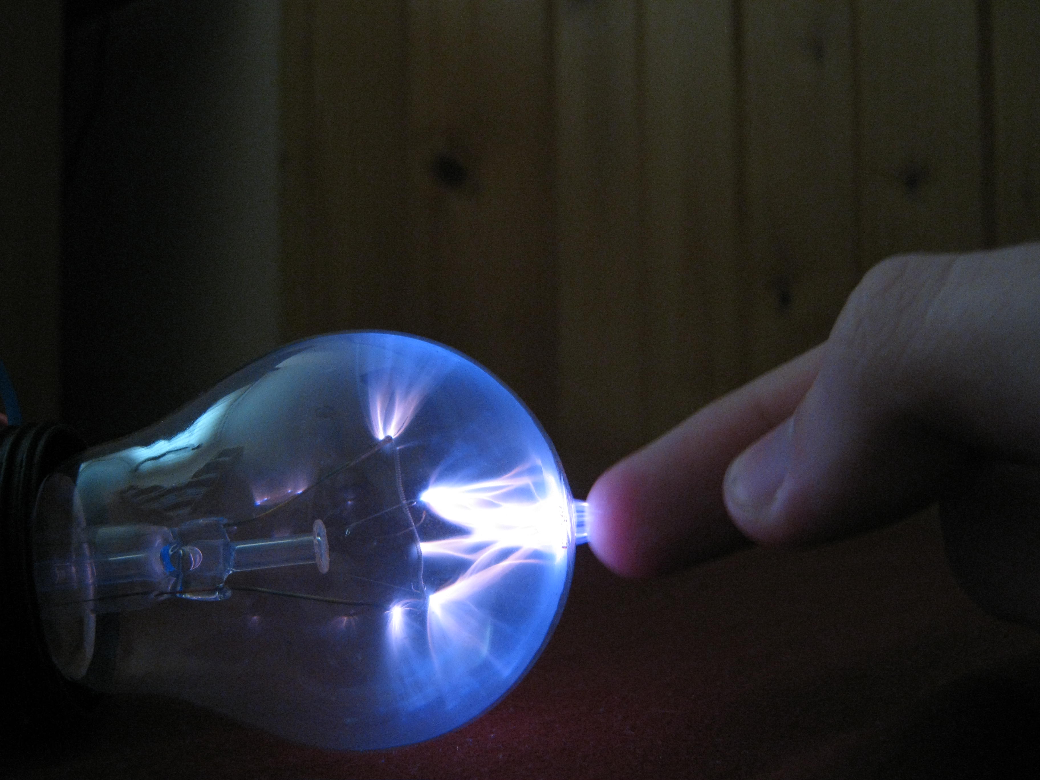
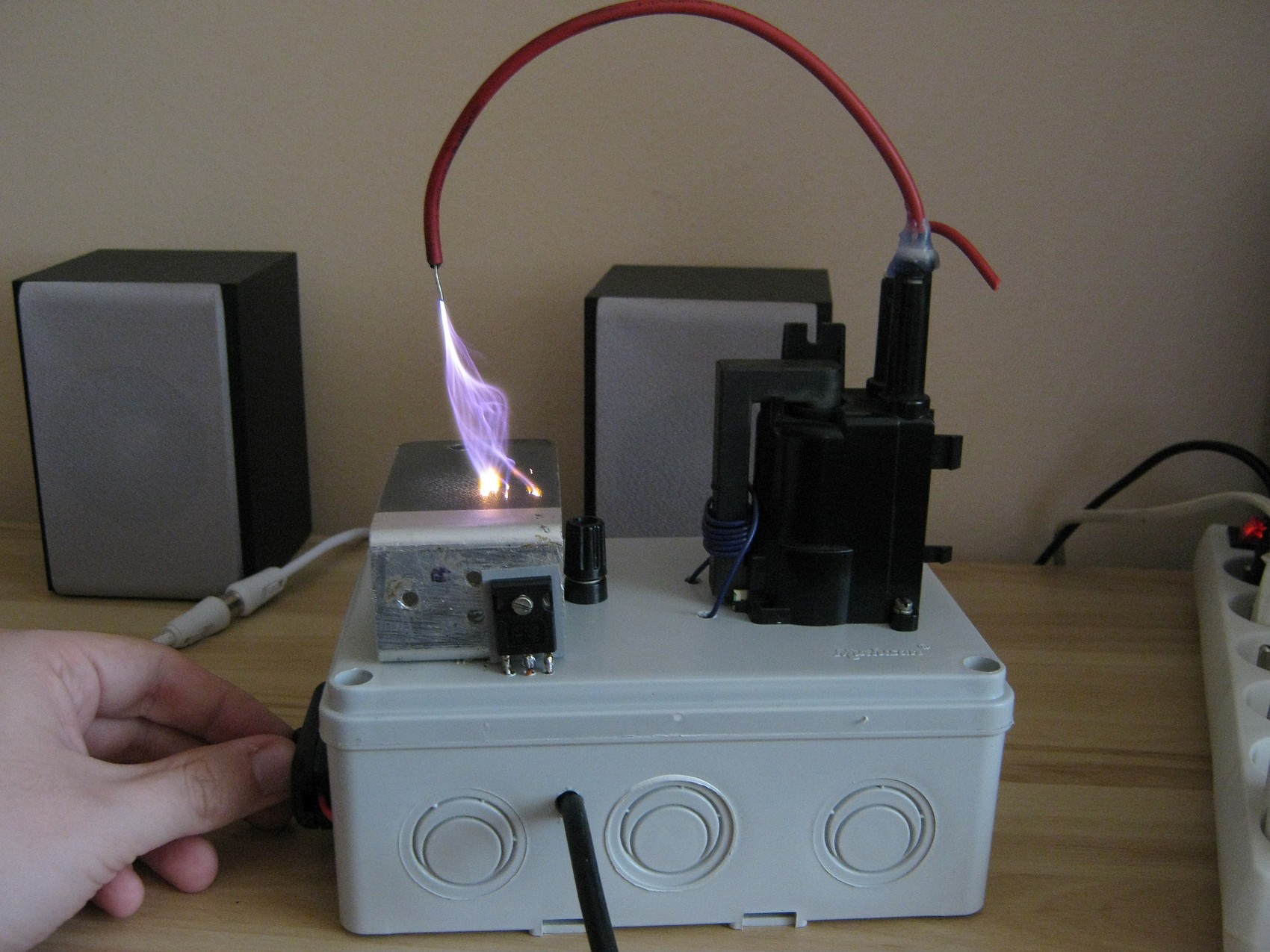
But to say the least, the first driver I have built with this topology had an AC flyback and an input power supply rated just 60 watts. The result was a compact, short-circuit proof, high voltage “lab” supply with frequency control, some active cooling, audio modulation (singing arc, or a plasma speaker), two 5-15 kV high voltage outputs (AC and DC) to play with things such as plasma globes, small Jacob ladders, multipliers, and so on. The machine, due to its intended purpose, did not provide big fat arcs – however I think it’s still impressive and worth mentioning. Behold!


High voltage enthusiasts, who are familiar with the classic NE555 flyback driver, will notice the foil capacitor across the primary winding, which really makes wonders. (More on this here.) The output voltage depends on the oscillator frequency (set it to variable 15-30kHz for output voltage fine-tuning), number of primary turns and on the resonant capacity. Fewer turns, lower frequency and lower cap values such as 100-330 nF are going to produce over 60 kV out of a DST flyback with ease; more turns, higher frequency and higher capacity (up to 1 uF) will yield smaller output voltage with more current. Tune these factors to get the best output which suits for you. Do not forget to include the gate protection circuit (diode+resistor) on the MOSFET, but if the resonant mode is not used, omit this. Lastly, use the fifth pin for PWM audio modulation – you are going to need a 0.5-1.5W amplifier for best results. If you are not going to use this, ground the 100n cap.
And now, the moment you have been waiting for:
The Monster Flyback Driver !
 More than 50 kilovolts out of a single flyback at 20 volts input
Tired of measly sparks? This flyback driver is for you then! To allow higher voltage inputs and bigger power outputs, get a separate 12-16V DC supply (a few watt transformer, e.g.) for the NE555 oscillator part. I do not suggest using a stabiliser like 7812, LM3xx’s since they are prone to the strong EMI this machine generates, and you do not want to fry the 555 chip with excessive voltage spikes… Then, substitute the “IRF5x0” transistor for a better type with at least 200V Uds and low Rds(on), i.e. IRFP250, IRFP460 or similar. Change the heatsink and the resonant capacitor if needed (a 330n-680n 250V AC MKT/MKP is enough), then connect the primary coil to at least 20 volts rectified d.c., and you are good to go!
I have given the nickname “Monster” to my second flyback driver based on this topology, because when you switch it on, all hell breaks loose. High-pitched whine, strong hiss and vast amounts of ozone are produced, high voltage wires are moving on their own, nasty static charges build up on everything conductive, strong ionic wind and corona discharge are felt even 0.5m far from the anode wire, some serious EMI is sent back to the mains: speakers buzz and hiss violently, ADSL router loses connection at times….These are just a few signs that the machine is alive and kicking.
When properly tuned, this topology draws between 3 to 8 amps on load, in a supply voltage range of 18 up to 2 volts, excluding the first example of my driver, which drew 3 amps and had been constructed for low power emphasis in mind.
Basically, you want to drive the flyback with a square wave between 15 to 30 kHz with a duty cycle between 35% (for low power) and 60% (higher power), but don’t oversaturate the ferrite core, or the flyback will get hot and short internally (especially old AC flybacks).
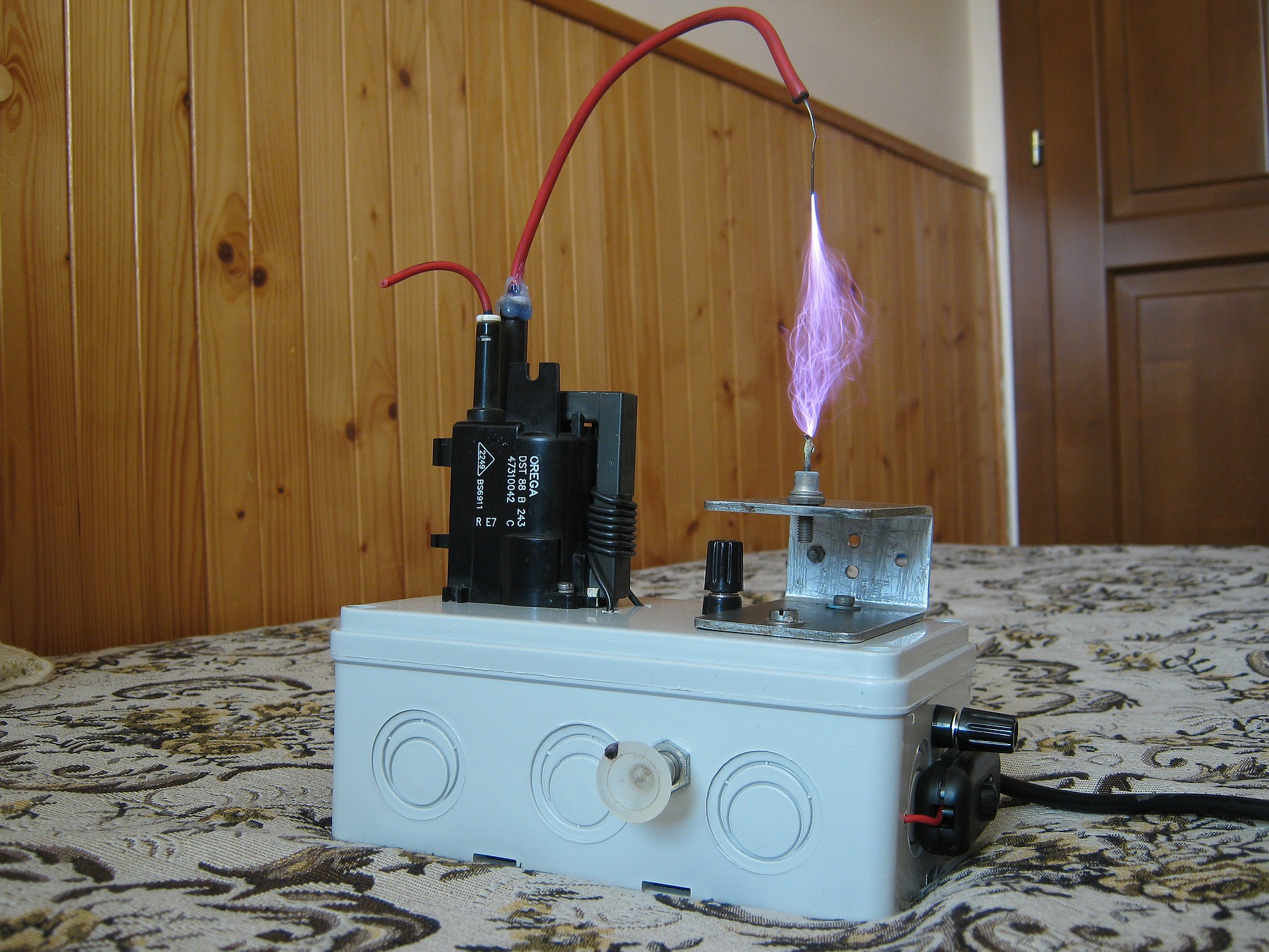
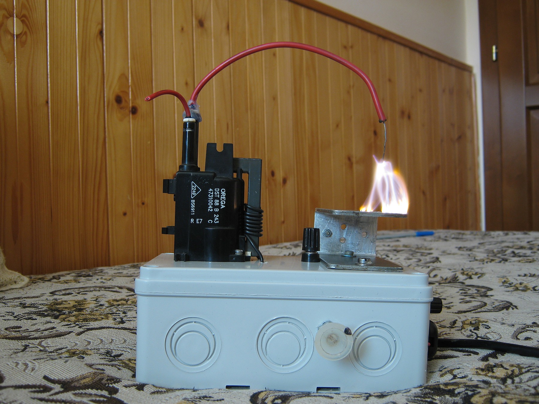


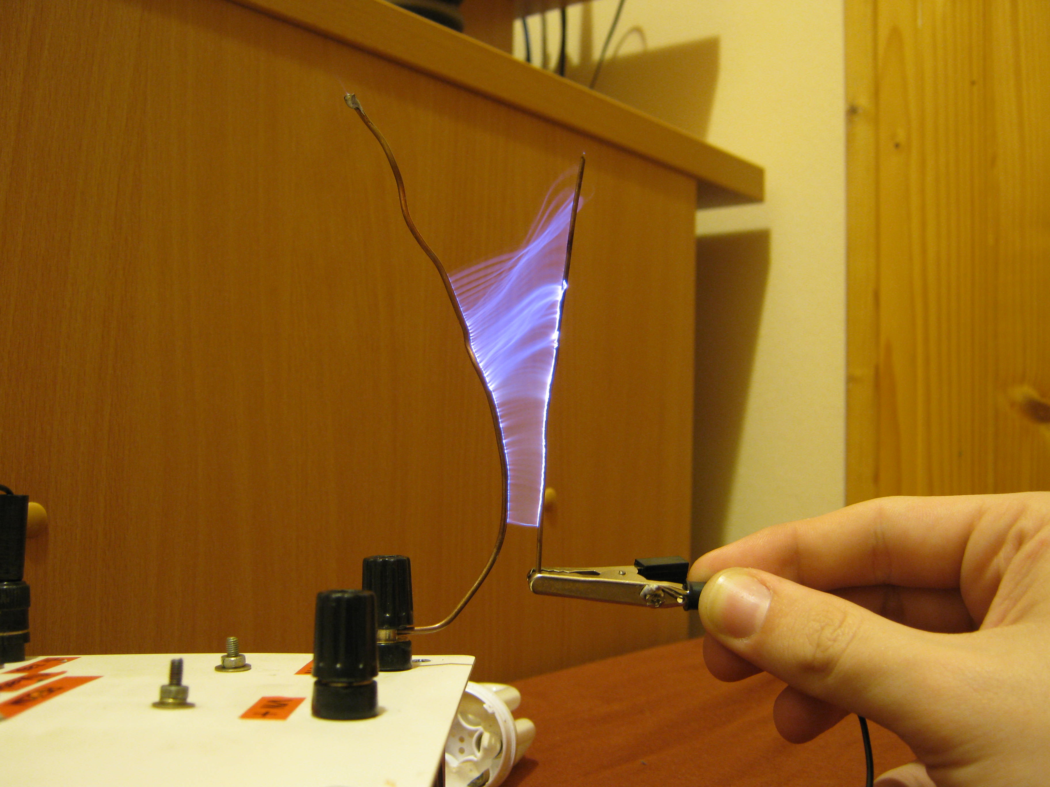
The thing you see here has an IRFP250N and the oscillator frequency is freely tunable between 16-30 kHz, giving an output voltage circa 20 to 55 kilovolts DC unloaded (at full blast, the arc ignition distance was 7.5 cm which might be roughly 50 kV). That corona discharge between the high-voltage anode and a concrete wall is also spectacular..
Pay attention to correct coil phasing, if using a DC flyback! You need to connect your new primary coil in a polarity so that the internal diodes in the flyback rectify each pulse in the forward way – otherwise you’ll destroy the diodes, yielding A.C. output on the flyback that will eventually eat through the insulation and fry the whole thing from inside and out.
To detect this, try connecting your primary coil in both polarities and then use a kilovoltmeter – or just observe arc striking distance at the same frequency and power supply you’re using. A correctly rectified flyback will yield more kilovoltage (bigger arc striking distance) when the polarity is correct.
Nevertheless, if you overvolt the diodes (especially with cheap small flybacks), the flyback will eventually fail even if they are forward-biased.
ESD protection (important): If you have a big flyback (like from a projection CRT) that can provide more than 50 kilovolts with this circuit, and your driver chip is close to the anode so that it accumulates static electricity, you can observe the driver chip AND the MOSFET become randomly destroyed with the flyback “hissing” free to air. If this happens, shield your driver properly, put it further away from the high voltage, and especially use e.g. 16 to 18 volt Zeners in anti-parallel with the gate of the MOSFET and ground, and also in anti-parallel with pin 8 and ground of your driver NE555, so that the static build-up gets shunted safely. A gate charge of more than 20 volts (or in some cases, 30) will kill the transistor instantly, and you want to avoid this.
Audio modulated “Singing arc”
Old prototype version
Hi there. Your arcs are exceptional. My own replication did not produce anywhere near the length and intensity of those arcs. I went up to 30v on input. A few things come to mind.
– My flyback transformer is physically smaller, from a black and white TV.
– Number of turns on primary is 10.
– I used a 2uf cap on primary, taken from a ceiling fan.
– I have built this to use it in a small chemistry experiment (Birkeland Eide process). I suppose even weaker arcs meet the requirement of heating the ionized gas to 3000degC but am not sure.
Your help will be greatly appreciated.
Hi, i want to used this circuit for my ElectroStatic Precipitator, and i am very noob with circuit. What if i don’t need the Audio? What should i ground it? What is RC1? Can you give me the tutorial in video please?
In doubt use an arduino for the pwm signal and a push-pull stage for efficient switching. A pull down resistor will not be enough for such high speed switching applications – oh an use a 15V TVS diode between ground and source as well as a. 10-20 ohms gate resistor or you will fry both the mosfet and npn.
I’ve used it to build an electrostatic filter for in vitro cultivation of fungi and bacteria under a sterile air stream myself. Make sure to use low duty cycles as you don’t need a high power, but high voltage.
I need help,
if I power the circuit, the mosfet gets pritty hot, but the transformer dosent create an arc
Hi,
Thanks for the circuit.
Can I use 20V power supply in transistor (IRFP250) stage?
The circuit works great, however I cannot get the singing feature to work. I tried connecting the output of various 5w BTL amplifiers to the cap but I get no singing. The amplifiers drive speakers fine. I also built a basic amplifier that overdrives my speaker (but I’m not really sure how to connect it to the circuit). Any chance you could include a link to the amplifier you used or briefly explain how you connected the audio to the capacitor?
The series cap just blocks the DC part of the input signal. To get the audio modulator to work, you also need to connect the ground of your sound source/amplifier to the common ground of the circuit, i.e. pin 1 of the NE555/source of the MOSFET.
Thanks for the response! You’re one of the few posters who have responded to my comments. The configuration you described is what I figured it would be, and that’s how I have it connected. I guess my amplifier is just not powerful enough. It is a little tiny Chinese board (https://www.aliexpress.com/item/1005001303007681.html?spm=a2g0s.9042311.0.0.27424c4dyySKOI). Also however, I cannot find a cheap amplifier board that is not in a BTL (bridge tied load) configuration. These typically power a speaker at twice the source voltage through dual operational amplifiers in reverse polarity, so when I connect positive output to the cap, I only get half the voltage output of the amplifier. Anyway I will keep trying to find something else, preferably something I don’t mind destroying just in case. Thanks again for the response, and for the schematic. This has been a really fun build.
Check the signal with a scope, or, try a direct soundcard line output of around 0.7 to 1 volt, something (not very loud) should be heard.
That works! I don’t know why I never thought to try a direct line in, I thought it just needed a higher output voltage or power on the amplifier. If I take the amplifier output and connect it to a speaker, and then connect the speaker to common ground with the circuit powered (plasma arc and all), I hear sound through the speaker, so I don’t know why connecting the amplifier output to the 100nf capacitor with the same configuration doesn’t work (for some reason this configuration also noticeably diminishes the current in the arc). However knowing that the line-level voltage does work eliminates so many variables to consider, so I should be able to figure this out now! Thanks again I am super excited.
Hello
I have some question about this circuit
1. How adjust 30kHz in this circuit?By using a potentiometer?
2. Is it possible to send a scheme of ” The Monster Flyback Driver”?
3. Is it possible to drive a ignition coil with the quasi-resonant topology with resonant capacitor?
Thank you
Hello, Jozef!
Very interesting solution. Is there a chance to tune this schematic in order to obtain a controllable HV power source 0-4kV?
The audio in can be convinced to get a 1V signal 10Hz and to amplify it up to 4kV?
Hi Jozef. Many thanks for your circuit! I have built it without the resonant capacitor/diode-resistor in the mosfet. I am using a 12VAC transformer which rectified gives out 16VDC for both driver and primary. I have also included a 10K pot and a 680 ohm resistor in series between pin 7 and V+ and this seems to allow me to control duty cycle (using the two pots I can get from “cracky”, whitish thiner lightling-like sparks to shorter, but more solid, bluish ones. I am testing two flybacks (one is AC, the other DC) and while I do get some 2 cm sparks, and ionizing wind, the diode bridge in the transformer gets really hot. MOSFET gets “reasonably” hot, it is mounted on a big heatsink, I am sure if I add a cooler it will run colder, but then again it is not the MOSFET which worries me but the power transformer itself. Neither the cable making up the primary circuit nor the flybacks get warm. Could you please advice? Thanks in advance, David.
If your bridge rectifier is getting hot then use two or more diodes in parallel to reduce forward resistance. Also use 10amp diodes like 10A05.
If transformer is getting to hot then increase number of turns in primary of flyback transformer. This will reduce output voltage and arc length a bit. Or try 10amp transformer.
Question: do you think this could be scaled down a bit to be used as a replacement for a failed HV supply for an air cleaner? The HV transformer in the device looks like a modified small flyback from, say, a monochrome CRT monitor. This unit will be left on 24/7 and, obviously, don’t want the HV supply to burn down.
Thank you
Hy,
I applied some of yours tips:
1) I isolated the driver from the wooden plank.
2) i cut off some wires and i tried to use just a few.
3) I isolated the MOS and its near to pin 3 of 555.
4) I add the anti parallel zener diodes : 12 V for 555 and 11 V on the MOS gate.
5)I do not use the resonant cap, so the MOS is directly powered by 11 V
And than comes what i couldn’t not applied:
1) I am using the breadboard because i do not have a PCB. I will buy some soon enough and i thought that when i will find the correct configuration i will make a real PCB.
2)The core does not have the steel spring, so i glued a wire on the bottom side of my FlyBack.
I checked the drain without the FlyBack and it works well: just, when is on high level, the signal is damped at the beginning. The power supply in my photo i use it for powered my Flyback, because the MOS and the 555 is powered by the battery pack and you see 5 V because i limited it at 5 V an 0,5 Amps to for testing.
So, in this configuration i still have the same problems: i visualized on my ‘scope the drain signal and when the arc is starting is horrible. The same thing for 555 output.
Actually did not understand how you connected the GND?
When you say main ground you mean the socket ground?
My ‘scope has “+” , “-” and also a socket ground.
So, between drain, core, “-” from Jacob’s ladder, “-” from battery, which goes to ground and which goes to “-” from powered supply???
Sorry for so many questions..
Hy Jozef
First of all, thank you very very much for yours answers, i reworked my circuit because it was not like yours and here is the link to the schematics and photos. Could you take a look to it and tell me if its OK?
https://easyeda.com/editor#id=c46d5092f7a4456b97c426fb08236f1e
1) The MOSFET is now supplied by a 12 Li-ion battery pack trow a 150 ohms resistor. Also this is the power supply for my LM/NE 555 timer.
2) My frequency is between 11kHz – 32 kHz and I change it with the RV2 in my schematics. For 11 Khz the duty cycle is from 37,5 % to 57 % max and for 32 KHz, is from 19 % to 85 %. The duty cycle can be change with RV1 as you can see.
3) I removed the filter and all diodes from ancient circuit to make it simple for my tests and i ground everything as can see in the photo.
Result: With 5 V, 0,5 Amps, 11 KHz frequency and 37,5 % duty cycle i fried 1 IRF 540 and two timers in only 5 minutes. But even with this low power i can get 1 cm arcs (unfortunately not for a long time). The circuit seems to be very efficient but the problem is that, the high voltage peaks destroy the transistor and the timer.
As you can see in the poto the GND line is a mess and also the signal on the drain of my transistor is oscillating.
I don not understand how this circuit works like that in your case and the others on you tube and in my case i can only burn out components.
Normally there should be a filter somewhere to stop the high voltage peaks. Could you take a look and tell me if something is not in order or if you have a solution for high voltage peaks?
+) You can’t have your Jacob’s ladder on the same wooden plank as you have your driving circuit and the FET! Wood is not an insulator – not at flyback output voltages. This is what I think causes half of your problems.
+) Your wiring is *ludicrously* long! Get rid of that breadboard and etch the smallest PCB you can for the NE555 driver. Use a DIP8 socket for a quick chip replace. Bring the MOSFET as close to the gate driver you can, and use the shortest wires. Also, put an insulating pad beneath the transistor and your heatsink, so it’s not at the drain potential and you can safely ground it. Also, use mains ground (PE).
+) Make sure the NE555 and the gate don’t see more than 15-16 volts, coupled from somewhere, or not. Use a 16V zener diode in antiparallel with pin 8 and ground, the same with the gate. Or shield the driving part well (with aluminum e.g.), then you don’t have to use the Zeners. If you don’t use the resonant cap in parallel with the primary coil, you can also safely ditch the gate resistor, in this circuit.
+) You cannot ground the ferrite core like that, you’re inducing a half turn short. Connect the ground to the steel spring that holds the two cores together, do not make a loop around the core.
+) Disconnect the supply for the primary coil of your flyback, keep the NE555 supply on and look at the gate with a ‘scope… Either that chink power supply in your photos is doing wonders, or something else. Clear that. Also, I see five volts on your meters – not enough at all to drive the chip, lest the gate.
+) Keep the duty cycle between 30 to 60 percent and the frequency between 15 to 30 kHz. Also the MOSFET requires at least 10 volts on the gate. This is the last time I’m repeating this.
Hy i write you again because i changed my configuration and actually i am using an 555 timer to generate the square wave which is between 1,5 Khz and 50 kHz with 50 % duty cycle and to be sure the transistor is saturated i send 8 V on it’s gate. I also buy new MOSFET transistors and i am using IRFP 460 ( 500V 20 A 280 W) but still does not work properly. I tested between 3 to 15 V and i can get 3 A and some 2 cm arcs but everything is going wrong because of electromagnetic interference. Actually when power grows up on the gate of my transistor the signal is really bad: most part of the time is high state and i thick i have to throw it away because without the power supply when the gate is connected to the pin 3 of 555 the signal is triangular… it acts like a capacitor. I also tried to add a snubber filter in parallel with the primary coil but then there is no arc Also i tried your configuration with a 470 nF capacitor in parallel with primary coil and the arc becomes very weak. By the way i do not understand the 800 ohms resistor and Uf 4007 purpose on the gate. How can it protect the gate.
Where is the problem in my system?
The post above is me: Ciprian.
(1) Drive power MOSFETs with at least 10 to 12 volts on the gate, no less.
(2) No, you’re not getting a constant 50% duty-cycle between such frequency ranges with a single NE555. It’s not possible. You’d actually need two chips to do that (or a proper gate driver). Actually, driving a flyback transformer below cca 10 kHz is a silly idea, you’ll oversaturate the core. And you won’t get a duty cycle of below approx. 53% without a fast diode in parallel with R2 of the driver chip. Construct the circuit according to the schematic, then work out your own perks.
(3) Did you ground everything, i.e. your driver supply, primary coil supply, flyback return pin and its ferrite core, all to one mains ground?
(4) What kind of a supply do you use anyway? Measure the voltage drop on load. Make sure you’re getting enough voltage for the chip and for the gate. No less than twelve volts.
(5) Makes no sense whatsoever adding a parallel load to your primary coil tank circuit, let alone any “filtering”. Did you observe such a practice in other flyback drivers? Or where did you get that idea?
(6) You can omit the fast diode and the resistor if you’re not using the resonant cap in the tank circuit. They are in the gate to account for the Miller capacitance of the MOSFET.
If using a resonant cap, use a quality polypropylene one, or HF ceramics (with a high (k)VAr rating). Regular crappy ones will inflate and blow up.
Hy Jozef.
Your projects is really nice, you did a good job. Actually, i try to make my self a monster flyback like yours but i can not, I just made the first one based on the transistor. I succeeded to get 1,5 cm arcs. Then i tried with an arduino to generate a square signal who’s frequency i can change between 30 Hz – 7 kHz. Here is diagram that i am using : https://easyeda.com/editor#id=1ef85cf9b6564aaab8cb8c31a69ad542
Of course, i tried many configurations: in the last one i am using just the NPN transistor BUT11AF with the flyback transformer. But the transistor get hot above 8 V. I am using a stabilized power supply 0 to 32 V, 6,4 Amps max and even if i give the maximum intensity it’s stops an 0,5 Amps. The voltage i can turn from 0 to 32 V, and the flyback stard to make that nice sound, but no arc. I am using 1 mm diameter wire and 11 turns and i thinck my flyback is 4A model. Please help, what should i do?? Thanks a lot.
Hi,
For a circuit like this to work properly, you need to make sure that your switching semiconductor (be it a bipolar transistor, or a FET, or something else) is switching off and on (saturating) fully, otherwise you’re gonna get switching losses. Which is what you are doing with that BUT11AF NPN, that originally belongs into the horizontal sweep stage of CRT monitors and TVs – you’re not driving the base with enough current for the transistor to saturate, so it just heats up and does nothing.
You’ll get much bigger efficiency with this not-very-efficient circuit if you use a FET with a low Rds(on) instead, because its gate is controlled by applying voltage to it. With a bipolar transistor you’ll need to think of an additional stage to drive the base and it still won’t be as efficient as with the MOSFET.
Also make sure you’re driving the flyback with a square wave in between 15 to 30 kHz with a duty cycle of 30 to 60% maximum. It’s a ferrite, not iron cored transformer – completely different topology.
Hi
I build this generator but it’s not working. My only modification is by using 3 cells of laptop battery instead of your power supply. Maybe I screw something up but where I have to connect ferrite and other HV pin. Please response
Thank you
Well, there’s your problem. Three lithium cells, when fully charged, give around 10,8 volts in series – on no load. That’s just barely enough to saturate the MOSFET, not even mentioning the current draw.
Firstly, disconnect the primary of the flyback, and check whether you’re getting a square wave on pin 3 between at least 15 and 25 kHz. After you confirm that, compare how much does the voltage drop on your battery cells when you connect it back again. I don’t think the voltage will be enough to even start oscillating.
plese help me out is this thing will work as a power supply of electrostatic capacitor??
is it flat dc voltage or ac?
Depends on which flyback you choose… you can use both.
To charge high voltage capacitors, use a rectified flyback.
hello!
in this paragraph: ” disconnect the primary winding which went to the positive pole of the previous supply and you are good to go!” what do you mean? i didnt understand exactly what to do! ive made the circuit, but i dont know how to go from here…
please help!
It means that you disconnect the primary connection from the supply that provides Vcc to the oscillator (NE555 pin 8) and use a different supply for the primary coil, sharing the same ground with the supply that provides power to the NE555.
Hi …I am using the same driver …it works but the MOSFET gets very hot ….I am using a org 260….and my power supply is 24 v @40 amps …..I only use the 10 amp connection….not the 40 amp one…..the problem is actually with the resonant capacitor i think… Can u subject a good capacitor value.
Sorry it’s irf260….not org?
Hi, something between 220n and 680n should do the trick.
This is not a high efficiency driver however, so make sure you don’t run it to short circuit for too long.
Would it be any problem if in place of the 800 ohm resistor was one of 820 ohms?
You don’t even need to use the resistor nor the diode, Short it, and just Remove RC1, it will work flawlessly
You can bypass the diode if you omit the resonant cap.
hola.. este circuito puede causar la muerte?
cuanta es la corriente a la salida
Keď si nedáš pozor..
It doesn’t work…..WHY!!!!…Ha just kidding….seriously though , some of the questions you patiently answered is admirable. Are you still around or did you open a portal with this shit? Doesn’t matter anyhow, I’ve been addicted since my first arc. Honestly , thanks.
Johnathan
hey ,
can you tell me the use of RC1, is this used as snubber ? If not what is the function of this capacitor ?
what is the function of ultra fast diode and resistor across it ?
why to avoid RC1 if diode and register is not used ? What is the formula to calculate the value of RC1.
why have you not used capacitor across drain and source of mosftet ?
thanks and regards
RC is a resonant capacitor. In parallel with your primary it forms a quasi-resonant LC circuit. The fast diode is there to account for the Miller capacitance.
Hi Jozef,
first of all, thanks for your circuit and the exhaustive article about it, it’s really well done. Recently I’ve tried to assemble it and it works perfectly; I’m very satisfied. I’d like only to ask your advice about a small doubt I have. I’ve just retrieved a big IGBT from a circuit (it’s a 20N60C3, with 600 V collector-to-emitter voltage and 45 A collector current) and I’d like to know whether it could fit your driver or not, since I have the desire to test the circuit at 35 Vdc (for my circuit I am now employing an IRFP250 at the moment) Should I try it? To me it doesn’t seem that its switching time is exaggerated, but I may be wrong 🙂 . It has a 28 nanoseconds TdON, a 24 ns Trl, a 151 ns TdOFF, and a 55 ns Tfl (these are the typical values according to the datasheet). Thanks in advance for your kindness.
Regards, Valerio
Hi,
MOSFETs work the best here. I mean, this is quite a low-efficiency driver to waste a solid good IGBT on. I’d cap the supply voltage to approx 24 volts with this drives, save the IGBT for e.g. a halfbridge..
What is IRF5x0
IRF5x0 mean IRF540 or similar mosfet, IRF640 , 250 , 260 etc 😉
Hi i was try to calculate how much the output with this circuit, can you show me how to calculate the voltage output, like a formula ?
I have some confusion about connecting the second supply for the primary, I’ve built numerous versions of drivers but this is the first time considering using a second power supply. How exactly is it connected? I get that you take the primary off the original supply rail, but do you leave the other side connected to the 555 circuit? Also, where does the negative of the second supply go? Is it DC+ from second supply to primary and RC, and if so, then what? I’m sorry for what feels like a dumb question, but as I have never used two supplies in a circuit, and as no one anywhere is very clear on what is to be done, in addition to learning all these things on my own, I am at a loss.
Nevermind I think I’ve got it
why my flyback just hissing and dindt see any spark?
Did you connect ground to the common pin of the flyback? If yes, the secondary might be K.O., try a different flyback. Also check your driver, probe the third pin of the NE555 chip with a scope, also the MOSFET.
Podrías estar debajo de 15khz de frecuencia en la configuración del 555.
Very nice description to get a good arc. I made the circuit and works fine. But the common in the circuit is about 20 V above ground and I get short-circuits. I almost burnt a computer nearby. Do you know why ? or how to fix it ? Thanks a lot
Ernesto
You might be having a ground loop somewhere, or you’re picking up capacitive current. Ground everything to one point (make the connections electrically good, i.e. no cold joints or poorly torqued-in screws), and keep the driver far away from things that are ESD-sensitive, since at voltages this high, the static build up is massive (you can even feel the ionic wind hissing from the anode on your hand).
Can you upload to youtube detail video circuit of new prototype driver.. I want to know the positive terminal primary coil and turn direction.. Please
This was made quite a long time ago, I no longer have the original driver. However, you just disconnect the original primary from the 12V rail and get a separate D.C. supply (at least 100 to 150 VA in rating).
Why does the schematic only have one transistor , but your build in the video has two? Sorry just curious, awesome project!
It was a work-in-progress. The TO-3 thing mounted on the side of the “lunchbox” was a blown 7812 stabiliser for the NE555, which had been subsequently replaced with a separate supply.
Good day, Jozef
Is it possible to use your device for a cold plasma (cold electricity).
Thank you!
dude, i was make flyback driver just like this scemathic but i cant get any arc at the hv output, i use bsc25-t1010a flyback transformer, the supplay of the primary coil is 24 v 2 a and common the ground i got my circuit burn out, i have been 3 times and doesnt work. what wrongs with that.
Check all your connections, see if the 555 is latching up, and if all else fails try a different flyback and remake the 555 circuit
Hey i have the same flyback how can the flyback be a problem?
Dobrý den,
postavil jsem si tento projekt doma, ale mám takový menší problém.
Moje ,,jiskra” je podstatně menší než ta vaše.
Nevím si s tím rady a prosím vás o pomoc.
Příjemný zbytek dne
David
PS: kolika ampérový zdroj zde máte? Já mám 3 ampérový, stačí to nebo právě zde spočívá problém?
hiiii,
can i use this circuit output as input to the Tesla coil??
For a smaller spark-gap coil, certainly. 😉
Hi again Jozef, my qustion now, is about the antiparallel diode that goes in the primary coil to avoid the high voltage sparks destroy the mosfet, Why it is not in your schematic?
Because it is not needed. Both IRF540 and IRFP250N transistors used in this schematic have one internally. In fact, only a few MOSFETs have it omitted..
Mosfet will not necessarily be destroyed if body diode is rated to take repeated avalanche.
Don’t be distracted by forward behavior of that anti-parallel diode, not used that way here.
This circuit relies upon it’s properties as a Zenier.
Ahoj, postavil sem ten první, menší obvod, ale mám problém. Na pinu 3 není žádná oscilace, pouze vstupní napětí. Takže mosfet sepne, ale už se nevypíná. Zatím sem měl se stavbou obvodů štěstí, ale teď nevím co s tím. Nemáš nějaký nápad? Díky.
Serus, odpoj gate FETu od budenia, poriadne skontroluj zapojenie, či si v ňom nespravil chybu a vymeň “šváb” za nový.
Zdravím, tak už to funguje. Vyndal sem čip a měřil sem piny a zjistil sem, že je špatný potenciometr. Nebyl kontakt. Takže jak sem tam dal nový potenciometr a už jede. Dává 2 cm jiskry při 12V.
No, takže máš čo ladiť 🙂
Hi Jozef, i am running it with a IRFP 460, and i am getting a nice square wave on the output of the 555, and on the Drain-Source. But when I connect to the primary, the current goes up to 3 Amps, and the transistor starts to heating up a LOT. I have tried some different frequencies but still the same. I tried with two IRFP460 and its OK. What could be?
Oh, and of course I do not get nothing on the output of the transformer
With two IRFP460s in parallel ?
No, only one, but i tried with another to check if the problem was IRFP.
OK I found the problem, i post here so people with the same problem can make it work.
I was using a lab power supply to run the 555 and the mosfet. The solution is to run 555 with one power supply( i use now 9V battery) and the mosfet and the primary with another ( I use the lab power supply), DO not forget to connect the ground of the two power supplies together,
Now it works!!!! thanks Jozef for this amazing circuit. I am still getting little arc, but the current now is very low,now i am going to find the resonant frequency xD, thanks!!
If your supply voltage is under 16V, there’s no need of having separate supplies for the chip and for the primary. To me it looks like your supply couldn’t sink enough current, or the voltage was too low to open the FET so its mode of operation was more like a heating element 🙂
For beginners, it’s generally not a good idea to use a “lab” power supply for similar setups such as this one, so in case something gets wired wrong you won’t fry your expensive rig.
Your best bet is a laptop battery charger that provides at least 4-5A at 18 to 22V.
Of course, do not forget to connect both supplies’ grounds, flyback HV return pin and ferrite core all together and to mains earth, just like in schematic.
¿Why the core must be connected to the earth? I dont get it. thanks
Simple: you’ll avoid frying your driver out if the anode starts arcing to the core (at voltages over 55-60kV from a single flyback, it sure will).
Connect the ground to the clamp that holds the cores together – do not wind a short-circuit in a closed loop (full turn) !
Help, this may sound stupid but my arcs are massive, i used a FM200TU-07A MOSFET pack and a home
Rewound flyback, and with it I am getting up to EIGHT INCH ARCS, and it keeps arcing to my primary from the high voltage output, any hints on how to stop this?
Try dipping the thing under epoxy or mineral/transformer oil. My personal recommendation is whatever you do, just avoid hot glue, it makes things worse.
Oh, if it’s a homemade AC flyback, oil is your best bet. High frequency HV just slowly eats through everything 🙂
If you choose transformer oil, be careful with enclosing the flyback, oils softens certain plastics and makes them brittle.
If you don’t care about the output voltage and it’s just for show, make a permanent “arcing gap” so that it doesn’t hiss free to air, charging you with static electricity, and also it won’t arc where it should not 🙂
Hey jozef nice project! Im having problemvwith my circuit,i built it two times but everytime it runs for few seconds and then turns off and never works again.. Please help
Hi, are you using a SMPS or a rectified transformer for supply? What rating is your supply?
I dont understand how you tune the frequency. Are there pots somewhere in the ciruit?
Yes, there’s one. This is a basic NE555 multivibrator circuit.
Dumb question sorry and thank you 🙂
Hi Jozef,
I need your help, i’ve made this circuit exactly as you did it (but changing the transistor for a IRFP460 and the resonant capacitor of the primary for a 220nf 275v), whith an alimentation font of 14v 1A. My question is that it makes sparks of a maximum of 2cm, do you have an idea that what’s happening in my circuit?
Thanks very much for your help.
Yes, increase input voltage and get a beefier supply.
Okay, thanks!
Do you think that an input of 20v 3.4A from a computer charger will be ok? What input did you use for these proyect? Thaks for your help ;D
Hi, try reading the article more carefully, all the details are explained.
Regards
I’ve got another question, which type of amplifier do you use for increase the sound of the arc? I need to know the brand of it or if it’s made by you. Thanks!
I didn’t amplify the signal; if you plan to, be sure to use a cheap amplifier..
has recibido alguna descarga en las manos o cuerpo ? si ? que sentiste
you received a discharge in the hands or body? Yes? what did you feel
Not from this particular supply.
Hi, terrific article. This is probably a dumb question but, should the secondary of the flyback be connected to ground or should flyback secondary be isolated closed loop?
I tried with secondary ground connected to primary ground and circuit went pop. =)
Yes, as in the schematic – ground the negative supply, the flyback and its ferrite core all to mains earth.
Hello, I am building this circuit. What is the best way to find the correct polarity for the primary coil?
With an oscilloscope. Or, run it on low voltage input with a kilovoltmeter in the output. If you don’t have either, try both polarities and observe bigger arc striking distance. The correct polarity is where the voltage (jumping distance) is the greatest.
muy bueno, por favor amigo, el diagrama, se nos puede enseñarlo? Gracias y saludos desde Paraguay
Hey! Great circuit! I just dont understand the purpose of the HS diode on the gate? Surely it cant be to block CEMF?! Is it maybee to block rf noise.?? I remember the 555 drivers of my youth, sucking hard. Even when you spent an hour tuning both pots perfectly, it still sucked, and turned the mosfet into a heater at 1a 12v
This is to prevent a parasitic turn-on of the FET because of Miller capacitance. You don’t need this if you omit the resonant cap (and subsequently, scramble eggs on the heatsink efficiently).
Hi I just got into flybacks……But i have about 13 of them sittin around and i like this but i wish i could use the original pins…
Taco, you could technically use the original primary if you built yourself a mains-powered flyback driver such as a (half-)bridge etc. It’s a terno if you don’t have the datasheets as you don’t know the parameters (the number of windings etc), crucial if you are engineering your own driver topology.
I think it’s not that difficult to wind a few coils of wire on that exposed primary as I did in my setups… the input voltage is also safer, things do not tend to go boom 😉
IC was burned when i used 12V battery. Why?
Most likely because of an error in your circuit.
i used R1k next to diode, Mosfet 540 and RC1 is 2uF. You can test for me. please. sorry about my English. it is quite bad.
Replace the chip and disconnect the FET with the primary, see if you are getting any square wave on the third pin. Then check the transistor.
Mimochodom, ja tiež neviem anglicky najlepšie.. okrem nej to môžeš u mňa skúsiť ešte slovensky, česky oder auch in Deutsch.
thanks. I will test againt.
Ahoj prosim tě, mam dotaz… Arc mi to dela ale jqko spinane jakoze 5s nic pak neco a takto dokola
… Musim zapojovat nejaky piny na tom flybacku ja tam mam zapojeniu jednu nohu na minus ale nwm jestli je to sprqvne dekuji!!
To znie ako nadprúdovka v spínanom zdroji. Ak sa jedná o druhú verziu driveru (so vstupným napätím nad 12V), daj tam trafo aspoň 120 – 150 VA.
Hi, I’m having trouble with this driver, I wired up the flyback and I don’t see any arc. The only strange thing is that when I connect the mosfet the amplitude of the waveform across the primary is only a 2-5v amplitude as opposed to the one between gate and ground which is about 11 (using a 3s lipo as a power source). I’m using a IRFP250. I bring the two secondary leads together and nothing. Can you help me out? (email perhaps?)
Well, then there’s something wrong with your setup.. 😉 What’s the current draw and the supply voltage when it’s all connected and turned on? Probe the third pin with an oscilloscope whether there’s a nice square waveform. Does the FET heat up?
Hi, could you suggest a flyback to use for this project?
Thanks!
For plasma globes, high voltage multipliers and such, use the old AC flybacks described in the article.
For voltages over 30kV DC, Marx generators, Tesla coils, ion motors/lifters, Xrays, use DC flybacks.
Regards Jozef
How do I connect more than 12v? Because I do not want to damage the 555
tanxs
How much voltage you used when you made the video? How much current?
Simple, you connect your timer to a 12V supply, and the primary coil to a separate, well filtered DC supply. I’ve used 20 volts out of a 120W laptop charger.
Hi,
It doesent work for me (also commented on your youtube video)
It doesent get hot and i get a nice square wave….until i connect the MOSFET (but its still ok)
No Hissing or anything.
Sometimes the 555 just blows/dies (without beeing hot)
I checked the wiring and its ok.
(sorry for my english)
I’ve built the schematic, but met a problem. When I connected the leads to 12V car battery, the mosfet’s heatsink got very hot and it’s middle leg unsoldered. No hissing, pitching or whatsoever. What may cause the problem?
Thanks!
Your timer configuration did not produce a square wave at the output and conducted all the time instead. By now, your MOSFET might also be dead.
Thanks for the reply, Jozef!
My timer is “ICM7555IPAZ CMOS DIP8 1MHz 60uA 2-18VDC”. Is it suitable for the purpose?
Hi, it’ll do. However since it is a CMOS variant I’d place it in a shielded box, far away from the anode.
Hi all. For classic PWM flyback it is important to have proper polarity of windings. When primary conducts secondary diode is reverse biased. I store energy in magnetic field during turn ON and release it when transistor is OFF. That is why on flybacks schematics dots are placed “diagonally” when on your schematic looks like both dots are positive when transistor is ON.
1. Is it important how I connect my primary in case of this NE555 quasi-resonant?
Cheers
Yes.
I have aproblem with flyback driver circuits
umm, can I use IRFP 250 with this schematic?
It’s written there it is possible.
Thanks for fast reply,
hmm it’s not working :/, but i did use 100nF capacitor instead of 10nF one , could that be a problem? is there any possible way to test the circuit without flyback?
Yes it could, the frequency will be ten times lower the flyback is designed to run.
When I woke up, I tried my circuit again, and it worked with the 100nF cap, I did touched 555 timer to see if it is well connected so i guess that was a problem,.. sparks are thicker but also shorter than with 2n3055 single transistor driver, I guess it will be better if I find 10nF cap and replace it.. ..Thanks!! 🙂
I read in comments below, you told to someone he should use 12V for 555 timer and 20-30V for primary coil, can you please quickly draw a schematic, cause I don’t understand how to separate it.. Thanks!
Just disconnect the primary coil from the 12V supply and connect it to yours. Then make sure both supplies are grounded to a common point.
thank you, I’ve recorded video and uploaded it on Youtube
https://www.youtube.com/watch?v=05qH42oPSiU |arcs only|
You can do way better than that..
yes probably, but my Timers keep burning :/
Strange. Make sure pin 1 is on mains ground and that the chip’s not near the high voltage output. Also take note of the maximum input voltage for the chip, don’t go above 15 volts.
It’s a simple schematic, you can’t go wrong with this much.
I was using battery of 10 – 12V to run the circuit, and in like 5-9 seconds of arcs, it just stop oscillating, I was able to hear Flyback slowing down until it stopped working.. , but I wasn’t using audio input, so I left pin 5 Unused, I forgot to ground it with capacitor, also I’ve added UF diode in reverse, Now It’s good, thanks!! 🙂
Great builds, Great arcs.
I have built a plasma speaker kit using a kit, but it is nowhere near as good as yours.
Could you email the circuit and list of components you used to build your Monster driver?
Thanks
Hi,
Love your website and Thank you for sharing your knowledge ,I have learn few thinks from you 🙂
I like to invite you to visit our High Voltage page. There you can explore, document and share your High Voltage Experiments
http://isparktube.com/
Regards
Do you work with tube Radios?
These resistor values ALWAYS lead me to Tube Radio Sites…..also the diode.
But verry cool!
your said for results we should use 150VA and 18-24V right???
can you tell me this 18-24V is peak value of voltage, if i use driver with 2n3055 then voltage which is going to fed into the fly back is of peak value 24V or i’ve to consider RMS value???
For the “smallGen” schematic, is it necessary to have a diode on the high voltage side of the secondary winding of the flyback? I am not sure what an EHT diode is and what the ratings listed are for??
Nope, it’s not mandatory. I’ve used an AC flyback with an additional rectifier to get both outputs.
The diode itself is rated 30kV 30mA.
Nice !, thanks very much !
I need help. (Sorry for my poor English, in fact my mother tonge is Spanish)
I build that circuit in my protoboard but I can’t get the same results like you, my spark is half centimeter long. I tried using two 3055 instead only one conecting base to base, colector to colector, etc, but I have not the spark I expected. Can you tell me how many turns of wire did you put in the flyback?
Saludos from Argentina.
Use a 12V supply for the NE555 and a separate, filtered 20-30Vdc 8A supply for primary. Start with a good heatsink, 330n MKP resonant cap and, 12 primary windings.
To increase power and output kilovoltage, decrease primary windings.
P.S.: My mother tongue is also not English.
can you send me your circuit information bcz mw too using two 2n3055 in my circuit
Love this circuit. Built it some time ago. Very stable
Hello,i am using one flyback dc of television this circuit is ok or not
Thanks
And my flyback contains a internal diode
And my flyback contains a capacitor its a one problem or no
Yes, this circuit will work with any kinds of ferrite-core flybacks.
To je skvelý driver, ale je to zvláštne, nebolo by lepšie náboj z GATE odoberať bipolárnym tranzistorom? Vieš čo myslím. Určite by to urýchlilo nabíjanie a vybíjanie a tým pádom by to malo znížiť ohrev MOSFETu.
Vitaj, nakresli schému jak konkrétne si to myslel. S tým zapojením sa dá dosť špekulovať a zrovna sa nejedná o nejaké dvakrát účinné, na to sú už iné topologie.. a nebudí ich prachsprostý časovač, ale poriadny gate driver 🙂
Tak jasné, gate drivery sú najlepšie, ale ja rád čo najjednoduchšie (napr. ZVS :D). Myslel som niečo takéto, že proste bipolár vybíja GATE.
http://www.eleccircuit.com/wp-content/uploads/2007/10/fly-drv2.gif
Inak fakt sa mi lúbia niektoré tvoje experimenty, si pánko 😀 Môžeš čeknúť aj môj Youtube kanál, nie je síce zďaleka tak “profesionálny”, ale mám tam niektoré na fest zaujímavé veci (gogo311)
Great work! I made this one too, nice circuit, works good, but I want louder sparks.
Glad you like.
For loud sparks, charge a capacitor at the output, or make yourself a multiplier.
Regards
have built similar circuit to this, but high voltage leaking back to 555 blows it up, I measured 190 volts on chip supply, tried all ways to stop it, no success, any ideas, thanks
Ground the driving IC, MOSFET’s source and the flyback transformer return pin ( + if it does not help, the ferrite core too). Hope you are not alliowing the output to hiss freely anywhere near the IC…
your scematic does not show pin 3 of 555 connected, can you clarify, thanks
I’m pretty sure it shows 🙂
sorry you are right it is connected, I did,nt enlarge image, I can see it now, I have used my circuit to drive a tesla I,m getting 4 inch sparks with 12v input,have also used it to drive two flybacks in series! very impressive,
In the schematic its written if RC1 not used short it, it will be open not short
The dashed line was meant for the short.
Very impressive. Please give model number of flyback and what model TV it came out of.
Thanks – the flybacks used here are generic 90s-2000s CRT TV ones as described in my guide to flyback transformers.
Built the circuit. Didn’t work. I must have screwed something up. Hooked up my scope to pin 3, didn’t even get any kind of oscillations going on.
Replace the chip..
The chip was brand new. I did switch it out. I did find some errors I made though. I corrected them. Now I’m getting pulses that are just spikes on a line. They are very small though. The amplitude of the spikes is in the millivolt range.
You might have fried it once more, check all connections, probable cold joints and try again.
Seriously now: if, constructing such a simple circuit like this, makes you problems, you should back away from the high voltage hobby… And far.
I do have a disclaimer up above, but I think I would not want to hear you have been killed by one of my creations..
I’ve actually been doing high voltage stuff for several years now. I’ve also successfully made several 555 astable driver circuits. I know the dangers as well. I appreciate your concern though. Anyways, thanks for your help. I’ll probably figure it out eventually.
I made a 120v version of this circuit, with the exception that I copied the TV’s RLC filter on the transistor. So far I have only used the original primary @ 120v. To get best power out I need to mod my driver to have Duty Cycle adjustment. I’m also getting no audio modulation, LM386 Audio Amp?
Other than that this is a Super Simple circuit & makes a sick HV Driver!
k2749 is good for this application? I do not have another power transistor for this moment. thanks…
show the surcit diagram
and i have a flyback of a monitor (i know abowt the high voltage capacitor)
plugted the transformer in a 555 surcit over a mosfed and a put a cuple of AA batteries and ive got like 3 milimeter arc
Nice generator.
I build a prototype according your schematic and it works fine. It produces a lot of Ozone!
In fact it have a little differences, because I used an old Samsung FSA-14A003 flyback. With 10 turns on the primary side, I noted poor performance, so I decided to use the winding between pins 2 and 3 of the flyback, and the results were very cool. For the RC1 I used a 2.2nF/400V cap and a 1N4937 fast recovery diode for the protection of the 555 IC (pin 3). For the MOSFET I used an IRF630B.
I have noted that the 555 IC, after 20 seconds, begins hot, Thus, I put a 10K resistor between the gate and the GND of the MOSFET, with the aim of guarantee it turn off. However I noted that was spend of time, because it takes no effect.
Why do you think the 555 IC is been hot?
That’s strange.. Does it get hot even when you disconnect the gate?
I’d probe the output with an oscilloscope to see whether you’re getting a nice square wave, both stand-alone and with gate connected.
IRF630s work here fine but their internal resistance is quite high so they tend to heat up.
Thank you Jozef.
I did measure the output with the oscilloscope and noted that the square wave does fade-out slowly. Thus, I did replace the 555 IC and now everything is ok.
I did tune the frequency for the flyback (39kHz) and the performance is really nice.
By the way, the IRF630B MOSFET is not heating so much. I did put a little heatsink and is working fine (at least for 2 minutes of continuous operation generating Ozone). The current seams to be small. I will measure some day.
Anyway, thank you for share your circuit and your experience.
Regards.
what is the input voltage and current of the power supply you used?and also what is the output voltage and current from the flyback?would a computer psu work for this?
The first low powered version used a small 12v~ 60VA transformer (rectified, ofc). The second was built with a 20 volt, 120VA SMPS – for best results, use a supply 18 to 24 volts rated at least 150VA.
by first did you mean the prototype? and could you please tell the output voltage and the output current coz i’m thinking of building a tesla coil with this and to find the value and the voltage of the capacitor bank i need to know them.
Also, thank you for making this post.
Yes, the first was meant the “white cage”, low powered dual output version.
To do a spark gap Tesla coil I’d recommend building a halfbridge or a ZVS but this ought do the trick for micro SGTCs just fine.
Regards
Hello Jozet
the best for my project is a multiplier and if possible with variable voltage
very difficult?
another application for these circuits DC is electrostatic painting
regards
Pedro
Good day to all
This monster generates DC?
The Amp is lethal?
thank you very much
Pedro pin
Well, it depends on how it is built.
Thanks for answering Josef
I need to build a circuit to use as delivered 50KV electrostatic flock for a machine must be DC.
If you can give me a help I appreciate it
thanks
pedro
This thing has no problems delivering 50 kilovolts unloaded when tuned right.
I am not quite sure what did you mean with “electrostatic flock” but I’d go with a diode split flyback out of CRT TVs. Or if you want to be absolutely sure you could make a multiplier, e.g.
Regards
Tell me, what another DST can I use? Because, I have no that. Thanks 🙂
It works with any kind of television flyback. Diode split rectified transformers from CRT TV’s, with a properly set air gap, worked best for me.
Thanks 🙂 Your driver is very cool. I’ll plan to make the device with NE555, I have one television flyback TVS-110L4 (made in USSR) for this 🙂 But 1st, I want to build a device with lamps (tubes) 6P45S, I have all elements for this, but no have more time 🙂
when i used a other mosfet it blow out. so i changed back to the irf 450 but now nothing happens. can it be that my 555 is broke? cuz i dit not use the diode and resistor at pin 3 to gate of mosfet.
can i use the IRFP450 instead of the IRFP250?
Yes, you can.
Anyway, I will make both drivers, the ZVS and this one. It will be funny! 😀
Parece que no tienes mucho tiempo para responder los comentarios …
Sorry?
It seems that you have not enough time to spend in comments…cause I put a comment a week ago but I don´t receive any answer. More or less, this is what I said above (I’m uruguayan so I speak spanish)
Well and what did you expect from me to say … ? Good luck and have fun.
I don’t know… something? 😀
I have just one question: Is this circuit better than the zvs driver? Because I have all the components to make the resonant zvs driver but not this one.
Greetings from Uruguay.
This circuit is nice if an intention is to get maximum voltages out of a flyback, by tuning the resonant capacitor you alter the efficiency, too.
A ZVS is more efficient since it pumps more current into the flyback, but it is difficult to get higher kilovoltages without stressing the flyback much.
At 12V input: How much voltage can you obtain?… with a zvs of course.
“With a ZVS of course”, and my article above is about something else.. 😛
How many kilovolts on output you get depends on your setup; i.e. your flyback, number of primary turns, resonant cap, input supply power (and voltage drop), etc.
Frankly, at twelve volts you’re going to be bashed with low efficiency as the MOSFETs are not going to get open to fully conductive states. I’d recommend at least 18 to 24 volts as a starting value.
I just need no more than 12 KV to operate a homemade Marx generator. 8|
Well that would suffice. In case any driver of yours would have put a higher voltage than you need, even if it’s not a regulated supply, it is possible to make a spark gap which is going to limit it (approx. 1kv per 1mm ignition distance, depends on electrodes, humidity etc, this rule stops working above 30 kV).
Damn nested comments.. have to get rid of them..
Ok, thank you! 🙂
Ok, ¡Gracias! 😉
Parabens, gostei muito, sou do brasil!
Nice site.
i salvaged a DIY PWM circuit with a TL494, push pull BJT driving the IRFS630A mosfet output transistor also a computer monitor flyback and carbon rod from carbon zinc battery
With a 13 turn primary, 30khz, 50%duty @ 12 volt it draw 1 amp and start arc at around 15mm.(of course the bottom pin spark together if its left floating).
I tryend adding the resonant capacitor(.47uF/250v) but that reduce the spark intensity/length alot.