Back in 2008 before starting with high voltage, I have made numerous experiments with flyback transformers and with simple single-transistor drivers, most of these were undocumented. However, this was one of my very first high voltage circuits and my first -electronic- circuits in general, which were marked with some success. The resulting simplicity of this circuit pardons the low output efficiency…
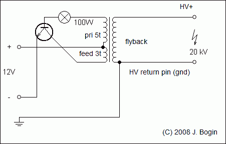 Schematic
This circuit, also incorrectly known as the ‘2N3055 flyback driver‘, bears some resemblance to the battery inverter/continuity tester which is published here. It is the same topology with almost the same “efficiency”, and it’s actually a nice example what happens when a primitive circuit like this is used with slightly bigger input powers 🙂 . High voltage enthusiasts surely know what I am talking about – this circuit is woefully unstable, inefficient, heats up immensely and it is seriously prone to failure when overdriven over 12 volts. The main reason is the lack of protection circuits, no stabilization, no control over the frequency, feedback and a lack of methods to improve this flyback topology’s efficiency. However, this circuit still serves its purpose: it is a gateway of every beginning high voltage experimenter to the world of arcs, sparks and alike (since it is simple to construct); plus the low output power makes an accidental contact with flyback’s energized output non-lethal. It will slap and kick like hell and maybe some minor burns might occur, however it teaches the experimenter to have respect before moving to more efficient and powerful drivers. And the output can also light up a candle easily (well, if the flame is not extinguished by the anode’s ionic wind, like in the video, unfortunately).
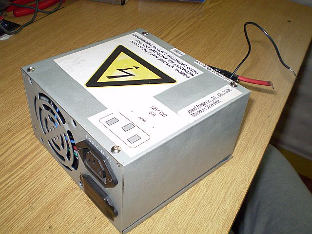 Flyback driver in a cage
The reason why I’ve put the 2N3055 driver in quotation marks is simple. This circuit isn’t precisely the “2n3055 driver” you have seen on other websites, as the two high-wattage resistors used in those schematics are replaced here with a single one – you’ve guessed it right, with a classic incandescent lightbulb. 🙂 Plus, almost every new 2N3055 you will come across at auction sites and e-shops nowadays will be counterfeit and made somewhere in the “Third World”, thus they are seriously underrated in maximum ratings, especially current ratings and breakdown voltage. For this reason I have used more sturdy bipolar transistors made by the former Czechoslovak TESLA, most notably the KD5xx and KD6xx series, which could take at least 2 times more abuse than the original 2N3055 made by the U.S. RCA company… However, let’s move on!
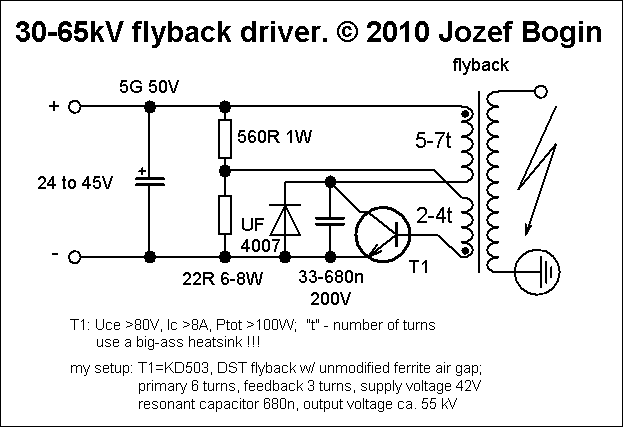 An improved version of the original driver
Well, after fiddling with ZVS drivers and similar halfbridge circuits I have returned back to the original 2N3055 driver approach. Then Jan Martiš, a Czech experimenter, came up with an idea to increase the efficiency of these flyback topologies: to add a resonant capacitor to the primary winding and tuning it afterwards to get the best output.
This circuit will remind you of the “international” 2N3055 driver you are familiar with. The principle is still the same, it is self-oscillating and has a feedback winding intact, but notice the resonant capacitor in the primary which really makes wonders. That fast diode is there to protect the bipolar transistor from excess voltage spikes. And that’s all, folks!
By tuning the resonant capacitor and the input voltage, you’re likely to get thinner arcs and bigger output voltage, or fat arcs and a smaller voltage output, or a compromise, or it will fail to oscillate. The last one happens when the primary/feedback/secondary windings are in incorrect polarity or phasing, or if the input voltage is too low (18-24 volts is recommended for this circuit). Likewise, the NPN must be heatsinked like in the first unmodified driver!
This is what I’ve got with a 330n resonant cap and a soft 40 volt power supply (a “soft supply” has a huge voltage drop when loaded,in my case I used a 40 watt transformer which couldn’t supply enough current to make “fat arcs” in layman’s terms, but because of that voltage drop it was still safe for the transistor to operate):
I have looked at your fly back circuit it’s a very interesting circuit. but there is one thing that’s puzzling me that is the capacitor across the power supply you have written it as a 50 volt rated capacitor but the other 5 g I don’t understand the capacitor value. so what should the value be something like 100 micro farad.thats all for now.
Currently it sounds like BlogEngine is the top blogging platform available right now.
(from what I’ve read) Is that what you’re using on your blog?
Hi,
if you’re new here, I advise you to read the Disclaimer which is located in the upper menu.
Also if you are a beginner in electronics I think you’re in the wrong section of this page.. 😉
Regards
Hello Jeff,
Great job, thanks for posting these!
Do you know if either of these would work with 12v coil from a car instead of the fly-back coil?
Thanks so much!
why we use fed back transformer in this driver circuit
In your single transistor driver can T1 be a substituted with a IRFP 450 ???
basé vous sur le circuit RLC pour le flyback les arcs sonts certes et petit peut moin grands et sonts en pulsation mais sans doutes plus puissants !!!!
Skús slovensky, anglicky, česky alebo nemecky, máš na výber.
I don´t really understand, Doesn´t the primary need ac or pulsating dc?
Forget the question.
Maybe I’m just no good at oscillators, but the first schematic looks wrong. The primary is fed through the base? That doesn’t make sense to me. Are the windings mislabeled? Or am I just not thinking straight?
Looks weird, doesn’t it.. But it works 😀
No, that’s a feedback “flyback winding” coil. the 2-4 turns provided really low voltage so it doesn’t burn the transistor. The primary is fed by the 50volt main line and modulated thereafter.
You are correct, in the first schematic the coils are mislabeled, the feedback (smaller coil) should go to the base, and not the primary as is shown.
HI, impressive results with a simple circuit. only thing I hate is the frying of the 2n transistor. even with a diode and a capacitor, it blew up instantly but hope I am just doing something wrong. I may use a mosfet instead. One question , for m more stable and higher voltages at lower current, is this better than a ZVS?
A note I’d like to add, I would broad avoid the 2N3055 of today as it belongs to one of the most counterfeitly made power NPNs , just take a look at their die size. That’s why I’ve put the “2N3055” in the article to quotation marks – it’s because of the transistor why it fails.
RCA, Tungsram 2N3055’s, Czechoslovak Tesla KD60x and KD50x work here just fine.
Alternatively, BUX22s can be used too.
@Anonymous, @Jozef, if you have possibility, you can take an old CRT TV or monitor and desolder a transistor that drive the flyback transformer. The transistor model was chosen by designer in a way that it won’t fry when operating with flyback transformer.
I don’t recommend using horizontal output transistors (HOTs) from those CRT TVs/monitors as they don’t work correctly in similar circuits such as this one; they tend to heat up and the output is measly. I think it has to do with the amplification (h21e) factor or base current..
On the other hand, if you built yourself a self oscillating flyback driver straight off mains, those HOTs would work fine. I’ve did it, but the circuit was unstable so I did not write an article bout it – https://www.youtube.com/watch?v=JqiPZdAc1nQ – and yes, it fried on the end 😉
hi mate, yeah its a output for the standard 2n driver but its still giving a good out put and it works well for a half bridge driver, I do like these 😉
thanx for sharing mate.
Glad you like!