Something I’ve crafted for the new X-ray experiments: a half wave, eight stage Cockroft Walton multiplier (or a Villard cascade, whichever name you like), submerged in oil, providing a theoretical maximum output voltage in excess of 220 kV with a maximum supply voltage of 10 kV AC, with headroom.
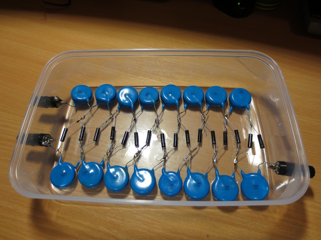
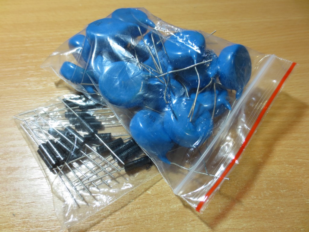 A bunch of capacitors and rectifiers
Sixteen 2.2nF and sixteen 30mA rectifiers, all rated 30 kilovolts, form the 8-stage half wave multiplier. Capacitors need to be rated for the peak voltage + reserve, diodes 2 times the peak voltage + reserve. In my case, as mentioned above, a theoretical maximum of 10 kV AC root-mean-square can be supplied (10*2*1.41, with a 2 kilovolt headroom). The circuit is quite evident from the wiring below:
Theoretical output voltage (that means, when unloaded, input is a sine wave, frequency is sufficiently high and excluding voltage drops on parts) is then calculated with a simple equation:
Uout = 2 * Uin * sqrt(2) * stages
where 1 stage equals to a pair of 2 diodes and 2 capacitors.
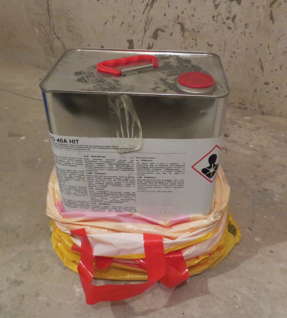
Of course, the whole setup needs to be submerged in oil, to prevent arc over and corona losses. I have used transformer oil to be on the safe side. Although clean and de-humidified vegetable or mineral oil will suffice.
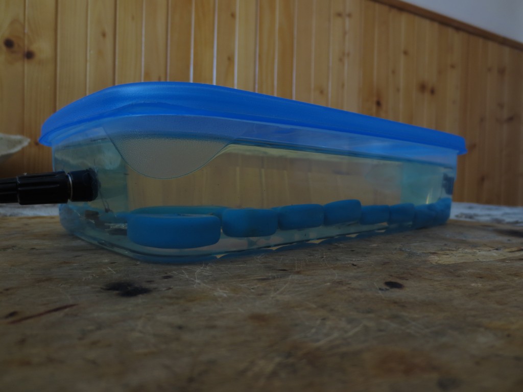 Under oil, leak test proved negative
If you have taken a look at the wiring above, you can say that the output kilovoltage is positive with respect to ground.
However adding a capacitor extra on the “unused end” allows you to change this polarity, if connected in reverse. In my “lunch box design” such an approach is not possible, because that’d need good insulation; to prevent pairs of terminals from arcing between each other.
If your approach leaks, seal them properly, and not with e.g. hot glue, as certain oils (if not all) dissolve it.
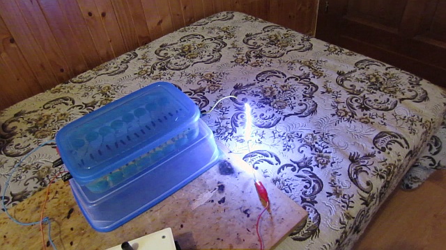 Fat 8 cm spark at 3 kV, 30VA, 12kHz input
The photo above shows the multiplier, fed with a limited square-wave AC input out of this small driver. At load, the supply voltage of such a purposely-low-powered driver drops to approximately three kilovolts AC, estimated by spark ignition distance. Which is good, as this setup was not made with arcs in mind (30 mA rated rectifiers).
This multiplier is used in the (upcoming X-ray setup), coupled with this ZVS driver and a Soviet 8kV AC flyback.
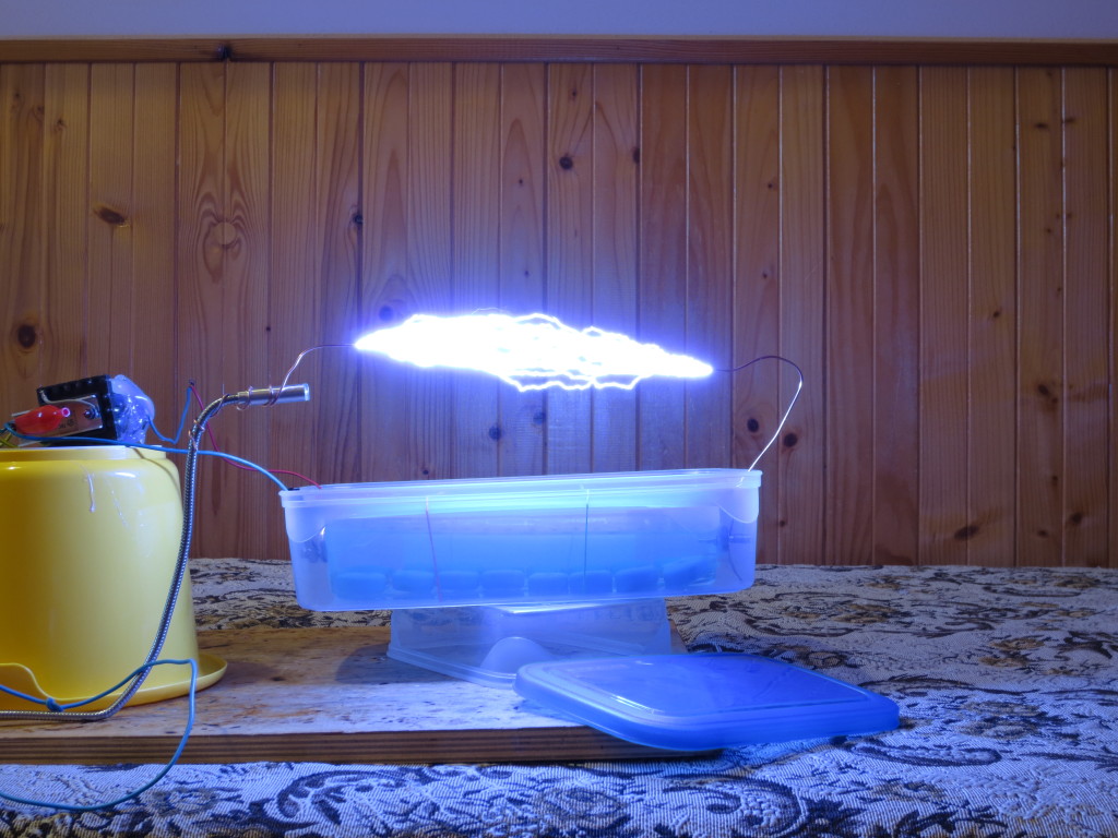 28 cm sparks (approx. 200 kV)
Input is a ZVS-driver-fed 8kV AC flyback
… and again
Great multiplier! I’ve used your design and added much larger caps (10nF, 20KV ceramics) and 2X in series 100mA 20KV rated (2CL2FM) diodes in a full wave rectification format. The output for 12 stages was 125.7 kV DC with peaks going up to 150 kV DC. The entire output goes into a freshwater shunting resistor @ 3 Mohm which brings the current down to 100 uA on the output similar to a Van De Graaff generator.
I want to build a small XRF unit with a small dental Xray tube. Wondering over what frequency input range the 2.2 Nano fd caps you used will work or are a different value caps more optimized for say a multiplier at around 30 Khz. And what value MA diodes need to be used for a tube that will never exceed 5 Ma. The smaller the cheaper. LOL Thanks Leo
Hi Jozef,
First of all congrat on the project, it’s really cool!
Could you please provide a basic a wiring diagram (with polarities) for that exact multiplier?
I know it simple, but I want to be on the safe side when making.
Other question is related to the grounding: is it possible to use the begining of the first connected rectifiers (or maybe one of the inputs)? Example: https://upload.wikimedia.org/wikipedia/commons/thumb/4/47/Full_wave_Cockcroft_Walton_Voltage_multiplier.png/220px-Full_wave_Cockcroft_Walton_Voltage_multiplier.png
I saw similar logic in case of Marx Generator, that’s why I’m asking.
Many thanks in advance!
Attila
Hello Sir. Nice work. Do you have the equations or formula to different capacitance of the capacitors? in addition to :
Uout = 2 * Uin * sqrt(2) * stages
Also, if you have any text book or the source of this equation, I would also appreciate it very much.
Thank you.
Hi and thanks for your comment 🙂
The circuit is basically a half wave doubler. Input voltage times square root of 2 means the peak voltage, multiplied by two as in “doubler” per single stage. That is then multiplied by the number of stages (one stage = 2 diodes and 2 capacitors).
Of course, this applies when the HV AC input is a sine wave, and you need to subtract a few tens or hundreds of volts, depending on your high voltage rectifiers and their forward drop.
Regards
In reference to the container containing the transformer oil. What do you use to stop any oil leakage after inserting the electrodes? Thank you.
Eventually I’ve submerged the thing into hot paraffin wax, since the synthetic transformer oil was very aggressive to the plastics. In addition I’ve also put molten hot glue gun sticks to the mixture which I’ve then poured in (paraffin is brittle).
Jozef,
Thank you very much for your prompt and informative reply, I appreciate your time.
I do have a few follow-up clarification questions for you, just for the sake of being precise, if you don’t mind.
First, when you state: “All you need to do, is to connect mains ground/earth/PE/PEN/whatever you call it, to the HV return pin of your flyback, that’s all. The high voltage outputs are then ground-referenced.”
Do you mean that the proper procedure to ensure that everything is referenced safely to ground, (literally, the Earth) would be to EARTH the chassis, and then connect the return pin of the flyback (HV return) and the negative of the low voltage portion of the power supply (ZVS driver) to the same ground bus, which is also referenced to the chassis?
What I am trying to grasp, is if it is safe to use a single, EARTHED ground bus for every return of the entire circuit, regardless if it is the low voltage half or the high voltage half. (And the chassis as well)
Again, thank you. Safety is my primary goal 🙂
Second, when you say: “I made myself one with 5x 200M 10W resistors submerged under oil + a 100uA meter, “”so 1u equals 1kV.””
This is a very small and probably obvious clarification, but you mean “so 1uA equals 1kV” correct? It just was typed “1u” so to be on the safe side, I am clarifying.
Have a great day, and thank you again for your time.
Hi,
Yes. What is connected to ground, has always a potential of 0 V (ideally, depends on the resistance). This is how lightning rods work.
Regarding safety, you really should be consulting your national standards, regulations and proper laws, and that’s something I won’t help you with. Frankly, a “lunchbox construction” such as the one you see above, is a working proof-of-concept which does not conform to any law regarding electrical safety. This is not a point of my webpage though.
But what I’ve mentioned in my previous post is just applied common sense. Connect the HV return pin of the flyback to mains ground and keep the flyback and the multiplier away from anything conductive – that’s all what is required. Enclosing the driver in a metallic chassis is not required (I didn’t), but if you do, ground the chassis also, to the same ground reference you’re using. Mains ground (PE/PEN) is sufficient enough, if that’s not available, use a water tap or a central heating radiator. The point here is that you really don’t have to ram a rod into the earth just to play with a high voltage multiplier 😉
The “1u” thing is a typo. Yes, I forgot the “little a” as in microamp. It’s just applied Ohm’s law, you’re measuring current in microamps through a resistor.
Regards
Good day! I have a couple more design inquiries regarding your ingenious setup.
Questions:
1. Grounding procedures
2. How to measure the HV out of the flyback so as not to destroy the multiplier
———————————————–
1. My first question involves proper grounding procedures, for safety reasons. Thank you in advance for your input.
To begin with, I am aware that when dealing with electrical circuits such as these, very high unwanted potentials can build up between Earth, and the low voltage line of the power supply, aka, (-), “negative”, “ground” “neutral”, “HV Return”, etc. in terminology. (I.e. for a DC system, even though the circuit has a “ground” and a positive connected correctly, the benefit inherent to connecting the power supply “ground” to EARTH ground, is to eliminate a potential shock hazard which arises because of a “floating” high voltage at which the un-earthed power supply can build up to, and rest at (So by touching the floating supply at high voltage, while providing VIA YOUR BODY, a lower resistance path to ground, one can be severely shocked).
I am wondering then, if you have earth grounded all of your (-) connections (including the HV return of the multiplier output), or if for some reason, you have not, because connecting all (-) lines to the same ground bus/chassis, and then EARTHING the ground bus, would cause some type of problem since perhaps the HV return/ground should not be connected to the “ground/negative” of the same ground connection as the low voltage, ZVS driver portion of the circuit? Perhaps due to problems that would arise since everything after the flyback transformer is magnetically coupled to the primary circuit…. (commonly grounding the secondary HV portion and the low voltage portion may be problematic…)
I apologize, I know that was a bit wordy. Basically, can/SHOULD one use a single ground bus bar for all negative connections within this entire circuit, and EARTH connect the ground bus so as to prevent high-voltage floating? If not, what portions should be chassis grounded and then earthed? ( initial DC power supply, low voltage flyback driver, flyback transformer, multiplier? Given the case of a single-box power supply design using this multiplier.) Perhaps the entire HV portion should be totally isolated from the low-voltage portion of the circuit, and just the low-voltage portion should be chassis/earth grounded? (DC power supply and flyback driver topology ISOLATED and earthed, common ground, with total insulation separation from this first half of the circuit and the secondary HV half, including the OUTPUT of the flyback transformer, and the output of the cockroft-walton multiplier?)
2. Regarding the un-rectified high voltage from the output of the flyback transformer, how were you able to determine its value? Since it is imperative that the high voltage, high frequency AC signal that is to be fed into the multiplier from the flyback is at a value that will not exceed the ratings of the capacitors/rectifiers resulting in destruction of the circuitry.
Normally, I would think that a spark gap could be employed. (Measure spark distance/length: dielectric breakdown of dry air VS voltage is a ratio.), But, since this ratio changes with AC current VS DC current, combined with the fact that the signal generated by the flyback transformer is a very nasty, dirty AC wave that is FAR from an ideal sine, I am wondering if the spark gap method would give me inaccurate results…
I considered a HV divider probe/multimeter, but again, I would think that this method would be plagued by the same issue of a dirty, distorted high voltage signal resulting in an inaccurate measurement.
I am wondering what the best method would be to measure/set the flyback output voltage (for the purpose of calibration to the safety limits of the multiplier components) if I already know that the input voltage to the multiplier CANNOT exceed 15 kilovolts.
Thank you very much for your assistance, and anyone is more than welcome to weigh in.
Have a great day.
Hi,
All you need to do, is to connect mains ground/earth/PE/PEN/whatever you call it, to the HV return pin of your flyback, that’s all. The high voltage outputs are then ground-referenced.
Just don’t let the flyback secondary or the multiplier HV output “hiss” to anything conductive which you haven’t connected to ground, be it the ZVS driver, or the heatsinks, transformers, et cetera. If that is not possible (e.g. due to space reasons), shield (enclose) the driver completely and ground the casing. So even if HV struck your chassis, nothing will happen to the driver.
The second problem here is static electricity. Make sure you’re holding a grounding rod so you don’t get a jolt after touching anything metallic which was near the multiplier (including you).
Oh and you seriously don’t want to make contact with the HV output, regardless if the supply is floating or ground-referenced … 😉
Per your second question: get a fast-recovery HV rectifier (found on the internet, or in some old TVs, they’re 20-30 kV diodes rated approx. 1 to 3mA), filter it with a small HV capacitor, say 1n0 20kV and connect this to a kilovoltmeter. I made myself one with 5x 200M 10W resistors submerged under oil + a 100uA meter, so 1u equals 1kV.
In this setup, the capacitor charges to the peak voltage of your AC flyback you have just rectified. (if it’s being fed with a sine). Then take a look at your meter to obtain the kVp reading. You can disregard the voltage drop on that single diode… At least this was my approach.
The “spark gap” technique is really a very rough estimate, and it’s based on observing the *sparking* (or arc-starting) distance. There’s a general rule of a milimeter per kilovolt between two spherical electrodes. However this really depends on air humidity, AC/DC current, or any external factor that might ionise the air and give you a false reading… and it also applies only up to circa 10kV, then it gets awry. (A 70kV DC driver of mine ignited sparks at 14cm…)
Your best bet is a fast rectifier and a kilovoltmeter/HV scope probe if you want to be sure.
Where we can get that monster diodes of 10-20 Amps diodes ??
Please forgive me but my knowledge about electricity is nil. If connect the output to a coil, will it produce a magnetic pulse with high gauss?
Is this statement true?
“I think I understand why [the output voltage remains unaffected]… since the resistor is open to air on one side, no additional “load” has been attached to the multiplier, so there is no voltage drop.”
I have been trying for weeks to an answer to this type of question, so any help that you might be able to offer me on this confusion would be greatly appreciated. I’m designing a cockroft-walton multiplier that takes a 15 kV peak input (not peak to peak, just peak) from a 30 khz flyback transformer ac output and steps it up to about 100 kV or so. I am planning on initially testing it using spark discharging and I am well aware that some kind of series resistance of very high ohmic value should be connected with the output (I’m placing it on the HV return arbitrarily) to avoid reverse breakdown of the diodes. Basically, I have a few concerns:
First, will the placement of the series resistor drop voltage? Or simply negate the high-current discharges inherent to sparks across the HV output of the multiplier stack? If the latter is the case, will connecting an arbitrarily capacitive load in series with the resistor and HV output cause a voltage drop?
I am assuming ohms law could probably be used for these calculations, but when dealing with these high voltage systems I am simply not sure that the same rules apply, which is why I’m getting a second opinion. Thanks again in advance.
Second, how is one to calculate the required value of the resistor to safely produce spark discharges without incurring harm to the multiplier rectifier diodes?
Third, as far as the power rating of the resistor, should it be rated for a significantly high wattage as well as ohmic resistance?
Thank you very much for your input.
Your HV resistor does not need to be high in wattage. If you are merely drawing a few sparks. However, it NEEDS to have large size (I placed 20 20Kv, 100kOhm resistors in series, zigzagged them to conserve space, and encased in wax).
If you do not encase in wax, then you need a physically large resistor, or the voltage will jump over the resistor to avoid being ‘resisted’.
Also, to calculate the resistance, look up the data sheet of your diodes. Mine are 2CL2FL resistors, rated for 100ma continuous current. Their PEAK is a 10A burst. So, in theory, if your multiplier outputs 400,000 volts like mine, use Ohms law: 400,000 = 10A X resistance, or, Resistance = 40kOhm. This would be the MINIMUM resistance to meet your diode’s max surge. However, you never want to reach your max surge. Try to limit a diode’s surge to 10% of its max, and it will last forever. I personally limited surge current in my multiplier to 0.2 amp sparks, as I am paranoid about wear and tear. Long story short, my multiplier used this equation: 400,000 = .2A X resistance. This gave me 2M ohm of resistance.
Scale everything to your multiplier voltage output, and, your diode’s surge rating.
Happy Shocking,
Jay
hello ,
I am doing this as a project in our college . Initially i have planned of doing 5stage multiplier with 230v ,50hz as input .So that i can generate around 1kv neglecting the losses that takes place. But i’m in a trouble because cant understand which capacitos (i.e their type and ratings ).. Will you pleae suggest me with the capacitos to be used?
sorry i have mentioned 230v but it is 100v input
That also depends on the output load current you want. Use at least 300V rectifiers (since it’s 50Hz, 1N400x series can be used) and for e.g. an 1mA load, I’d suggest a 4-stage multiplier with 4M7 200V non-polarised caps. More on this here .
I am also doing the same project. Please do provide me the whole circuit with the ratings and capacity, model of diodes and capacitors. Nikhil did u succeed to complete that project. Please do help me.
how to decide the no. of stages to b used
That’s entirely up to you and your application.
Brilliant results man. I just finished a 10 state multiplier myself. It works great at only 1kHz input. Cant wait to build a higher frequency input!
I have a question: have your caps ever degraded / your spark performance degraded over time? Basically I’m curious if running the sparks without a current limiter will damage the caps?
Hi,
Drawing sparks won’t harm your caps, but you ought to use diodes with a bigger surge current rating. Some folks use fast 1kV/1A rectifiers (BA159, UF4007 etc) stacked in series as one HV rectifier in the bridge. Of course they’re soaked in something non-conductive, or are rolled inside some plastic tube so the corona losses are minimized.
As this multiplier was originally planned for more X-ray experiments, my rectifiers were rated 30 mA only.
Regards
Thanks for the comments. I am currently using 100ma, 30kv diodes. They work great. They have a surge rating of 10A, but I try to keep spark amperage at 5A. I only use a 20KOhm water resistor on the output. Does spark length increase or decrease with increased resistance on the output?
I presume your 20k resistor is in series with the multiplier output – the output kilovoltage measured at open circuit (“spark jump distance”) won’t be affected much.
I think I understand why… since the resistor is open to air on one side, no additional “load” has been attached to the multiplier, so there is no voltage drop.
Great. Cant wait to make an even larger multiplier.
Will You plz let me the the diodes that you have used. as in like UF4007 or 1N4007.
Those were HVRL300’s. However if you plan to build it for arcing and stuff, you’d better use beefier diodes.
Awesome setup I have 20 – 10 amp 100kv diodes ( monster sizes) and i have been wondering what to do with them… now I know!