The ZVS flyback driver, made popular by Vladimiro Mazzilli, is one of the most efficient and powerful flyback drivers used by high voltage hobbyists from all over the world. The main advantages of this driver are simplicity of the circuit itself, very high efficiency and easily obtainable parts. By tuning it properly you are able to get insane power outputs; beefy flyback transformers will sustain a kilowatt for a short period.
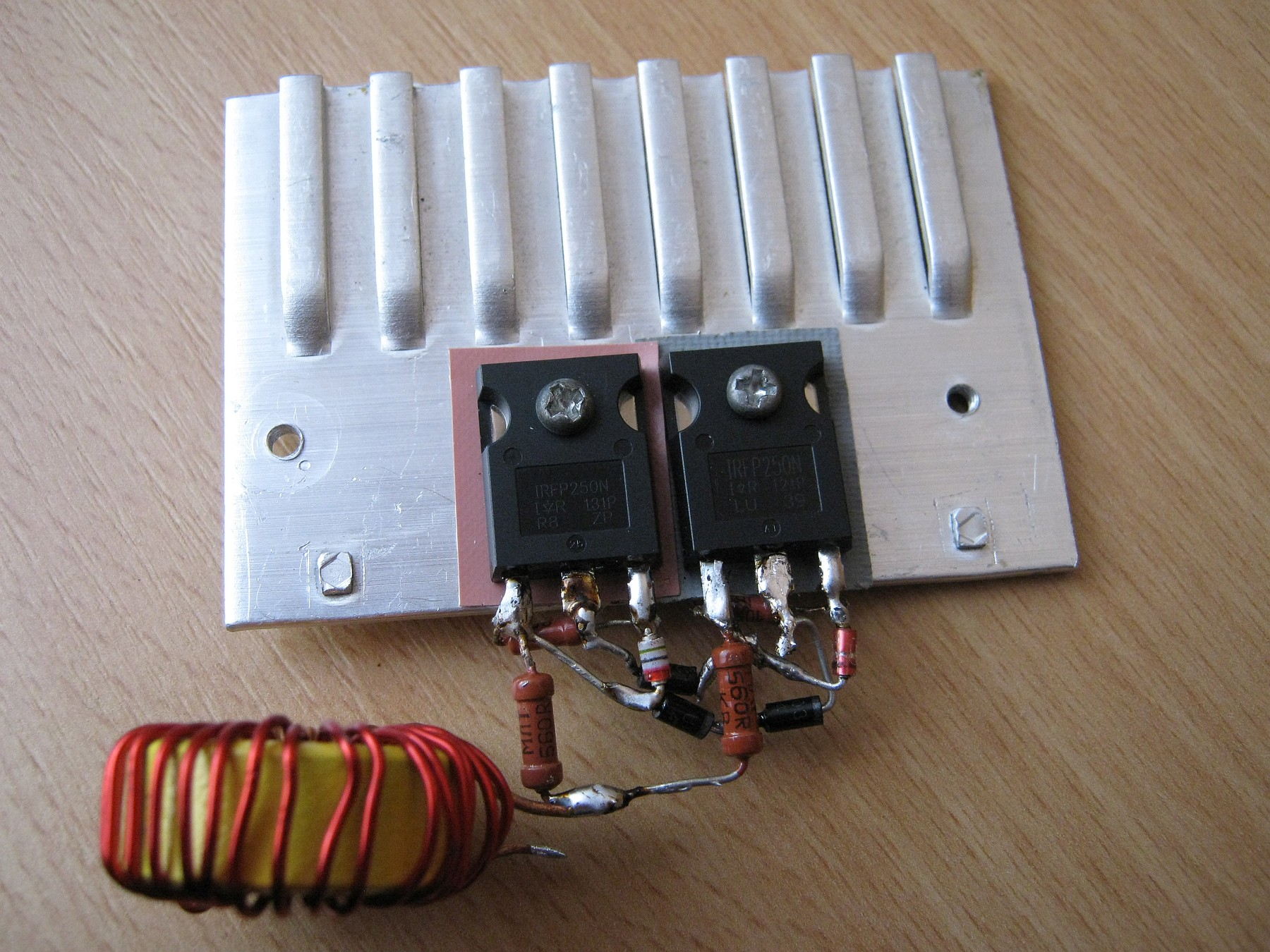 1/2 of the whole circuit
The main workhorses of this circuit are the MOSFETs, input power supply and the resonant cap. Two fast, identical MOSFETs have to be used, with maximum drain-to-source voltage approx. 4 times the supply voltage, and drain-to-source resistance while on, below 100 milliohm. The higher this value is, the lower the efficiency you get, because more heat is generated between D-S. So, you’re safe to go with IRF540s (55mOhm Rds) if your supply voltage is no more than 30 volts, or IRFP250s up to 50 volts. My first version of this driver had two IRF540s and a voltage of circa 35V on load, and it worked flawlessly. To be on the safe side, don’t forget some heatsinking (and mica insulator mats if you decide to use a single heatsink, or else you are going to short both drains out).
 Internal connections
The second main factor is the resonant capacitor. From my experience, use the physically biggest you got with a >250 volt rating. Do not try to use ceramics, or God forbid electrolytics; you will need some good “MKP” polypropylene (or “MKT” polyester) capacitors in the 100nF-2uF range. The reason why I have mentioned “physically biggest” is because you need to search for those with a high kVAr rating (kilovoltamperes reactive power), or else the capacitor will overheat, inflate and fail – sometimes with an accompanied “bang” 🙂
Use lower capacities, like 220n or 330n to get higher output voltages and lesser currents, and higher capacities like 1uF for some fat hot white arcs at 20-30 kilovolts out.
If you want to be perfectly sure, get at least 2 or 3 of these MKT or MKP caps and wire them up in parallel. This way, they are not going to heat up so much.
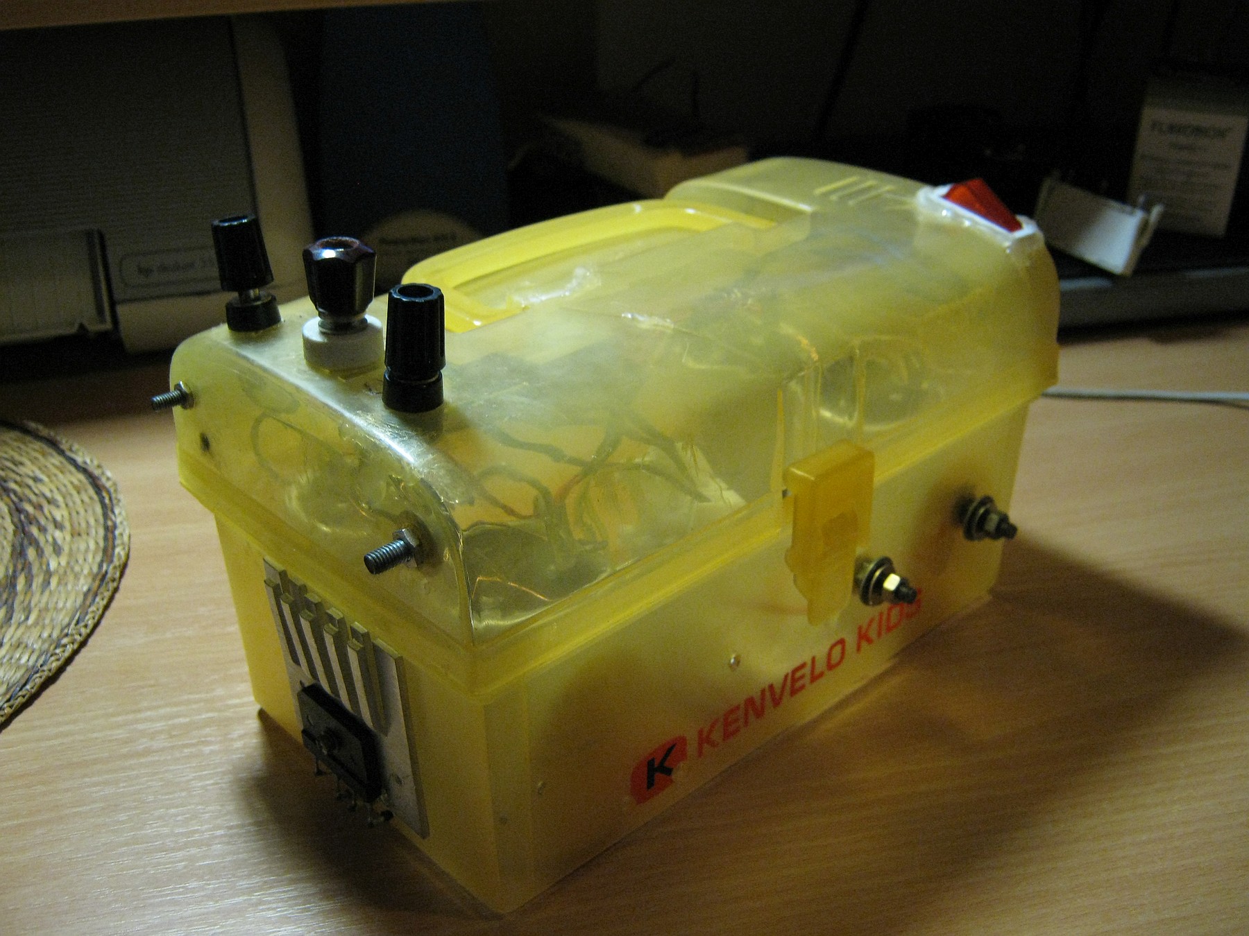 Third version of my driver, caged
As for the input supply, get one which can give at least 24 volts DC and 10 to 16 A. Be sure to take the voltage drop at load into consideration. If your supply is working at mains frequency, you will need some hefty filtration caps; at least 10 to 15 mF is recommended to get rid of that mains hum. Also do not forget to heatsink the rectifier.
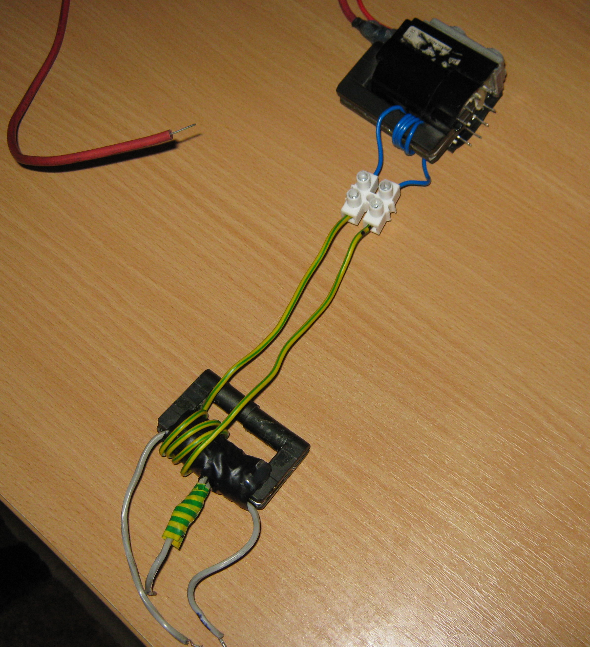 My “driver” transformer approach
Now, this driver is really good when it comes to efficiency and output current in comparison with other topologies, however, it is quite difficult to obtain more than 40 kilovolts out of a single DST flyback without increasing input voltage, thus stressing the components more, or without an external high voltage multiplier.
So, my approach was to drive two identical DST flybacks with their secondaries in series, through an insulation “driver” transformer on the primary. However, phasing must be wired in correct polarity and the secondaries must be built exactly the same, or else it will fry the internal diodes out. This idea has been thus scrapped.
Nevertheless, I have managed to obtain circa 55 kilovolts from a single DST flyback, with 45 volts DC in, with a separate, “driver” transformer method. For this to work, I took some two ferrite cores out of a fried flyback, glued them together and wound 4+4 “primary” plus 4 “secondary” turns, in the same direction, primary was located directly beneath the secondary. With this setup, the 4+4 primary was connected to the driver itself, the 4 turn secondary to some 3, 4 or 5 turns which were wound on the flyback (check the photo or videos for more information, it is pretty self explanatory). This setup alters the resonant frequency; better than a directly wound “4+4” or “3+3” primary on the flyback itself would do. My approach results in lower current and lesser stress on the parts, too. However, you will have to experiment with the tank circuit, number of turns and with various flybacks for this to work the best for your application.
Just a note, this “driver transformer” idea was used in my third X-ray setup.
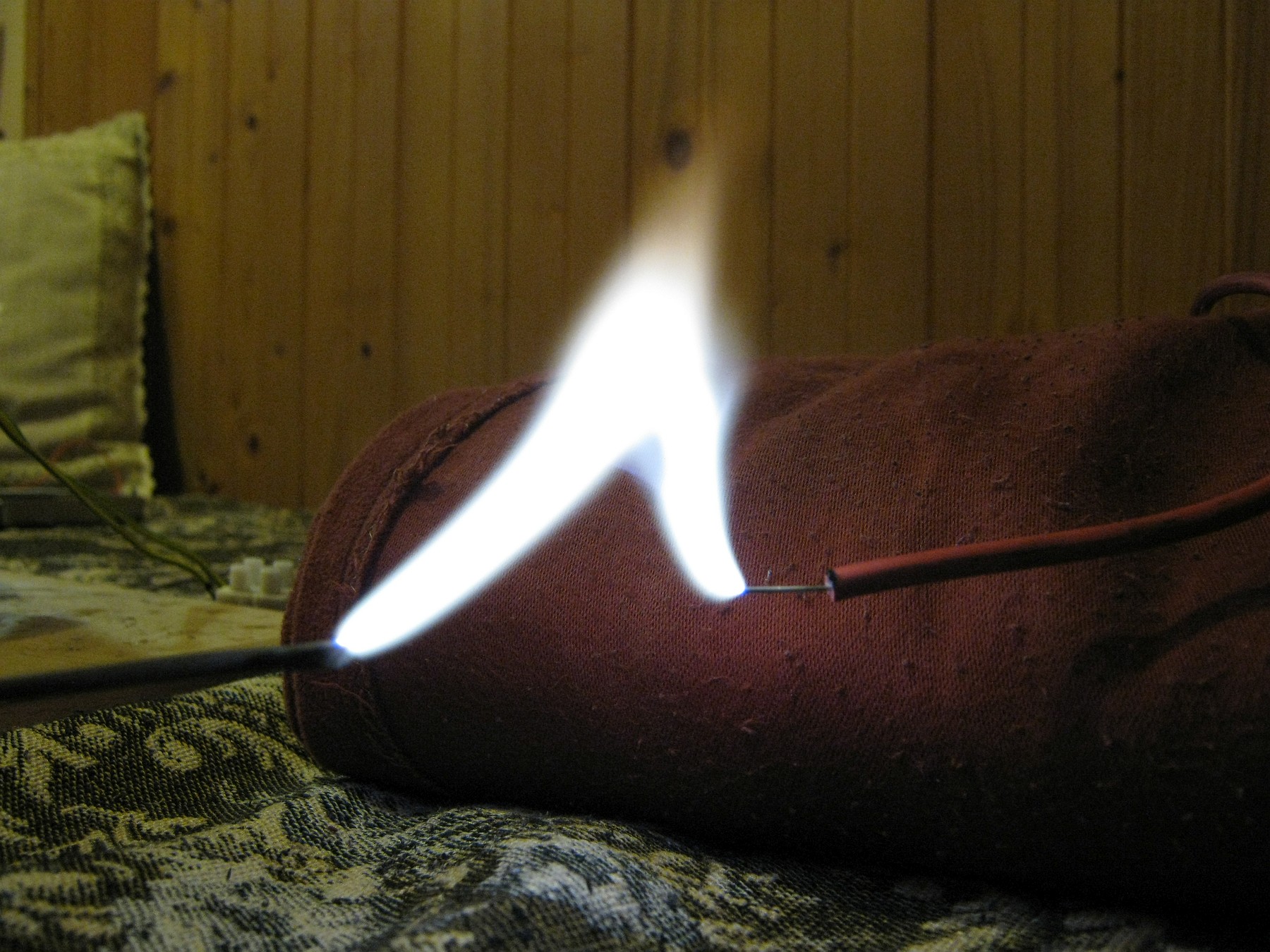
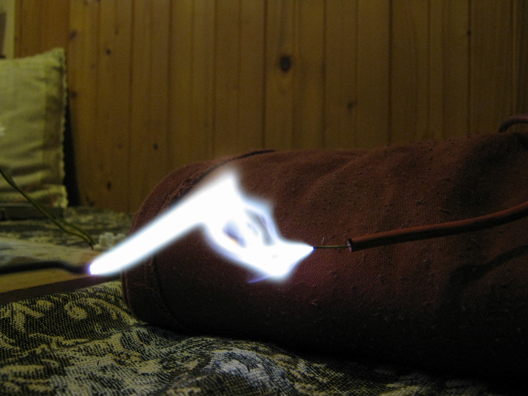
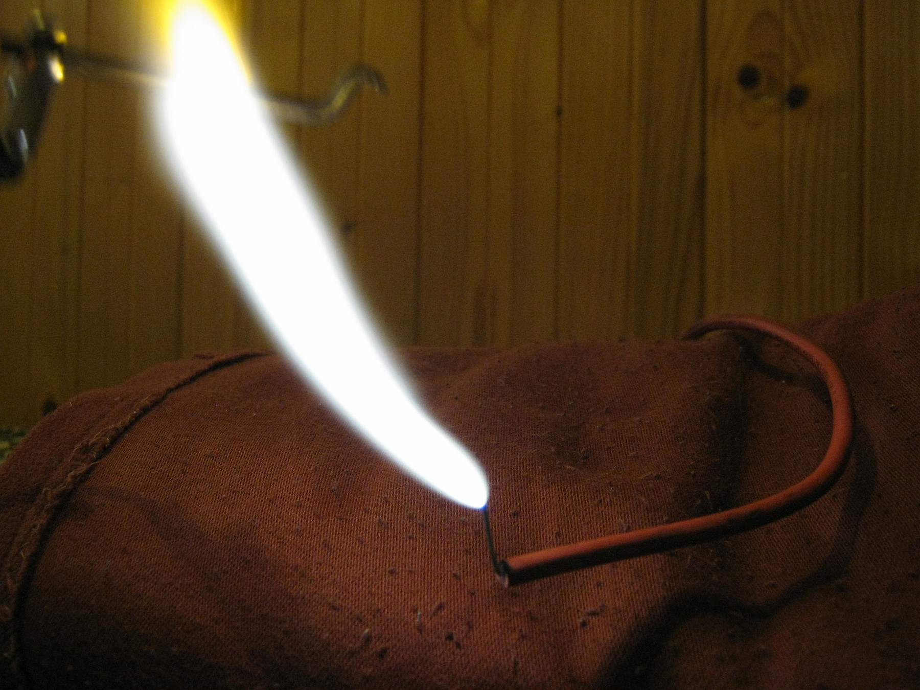
Some arcs:
(at 45 volts in, 30kV out, 2x IRFP250s, 1.5uF resonant cap):
 Videos:
My first ZVS driver, with IRF 540s
Jacob’s ladder with the IRF540 ZVS driver
A second version with IRFP250s and a Soviet AC flyback
2nd version, with the ferrite “driver” transformer at the end
My very first working X-ray powered by the “driver” transformer method
 The scariest voltage output I’ve ever got out of flyback transformers…
Here’s an insanity – a twin flyback ZVS driver – driving two DST television flybacks with secondaries in series, with the “driver transformer” method – more than 75 kV output, arcs *ignite* at 15-16 centimeters! 🙂
I could Place the MOSFET transistors Two igbt ?
im no expert but most likely would be less powerfull i think unless you make a full bridge igbt driver
Can i use Microwave oven Capacitor as C1 in the driver?
it is rated 2100V and 0.91uF?
here is an image- http://i.imgur.com/4KlEp6F.jpg
And should i use this modification of the driver-
http://www.instructables.com/files/orig/F7Y/CH9S/G9NH8XOF/F7YCH9SG9NH8XOF.jpg
Just to be sure, are flybacks AC or DC in this setup?
Also, which method is better for “higher quality” voltage.
50kV trippled in CW multiplier to get 150kV, or 10 kV flyback or neon transformer in 15 stages CW cascade to get to the same 150kV?
The best results I got with this setup is with a 8kV AC flyback (found in 1980s TV sets, these were coupled with a 8 to 20kV multiplier) as they sustain hundreds of watts of output power before you need to cool them. Also using the “driver transformer” you can drive two DSTs in parallel with secondaries in series to get 70-80 kV (as in the picture above).
For your question, if you want a multiplier, go with a high frequency supply as you’ll get far lower ripple and more output current (- old neon transformers run on mains 50Hz).
Rate the caps to peak voltage with a good reserve, diodes see 2 times peak + some reserve. This means if you have a 50kV rms (sine) supply, you’d need capacitors rated 75kV and diodes 145kV at least. 😉 Certainly go with the 10kV flyback, you can use lower ratings – I’ve did the same thing and obtained ~200kV: http://boginjr.com/electronics/hv/multiplier/
Great reply, thank’s.
Now I wonder if resistors are needed in CW multiplier since one sees them a lot in commercial and advanced hobbyist supplies like Glassman and others:
http://www.celnav.de/hv/hv4.htm
http://www.pocketmagic.net/wp-content/uploads/2011/03/glass3.jpg
I am looking more to build a full wave CW and drive it with ZVS and:
http://www.ebay.com/itm/271393125860?_trksid=p2055119.m1438.l2649&ssPageName=STRK%3AMEBIDX%3AIT
Your “driver transformer” with two of those above? But as you said, easier and cheaper with lower HV in and a couple more stages. All this is meant to be a power supply for X-Ray tube 125kV, this one:
http://www.ebay.com/itm/171512884325?_trksid=p2057872.m2749.l2649&ssPageName=STRK%3AMEBIDX%3AIT
That’s why I can not use opposite + and – stacks. Cathode must be at ground because of filament heating supply.
So, am I on the right track with this in your opinion?
ZVS + 15kV AC flyback….then full wave CW….10 stages (10nF/30kV caps, 100mA/30kV 100ns diodes) to power that tube above?
Later I will try and find some way to monitor “live” HV from output….likely to copy that Glassman schematic above menioned.
What do you think?
If you want to power an X-ray tube – with some reasonable current, you’d be better off finding an X-ray transformer and submerging it in oil. In some cases you do not even need to rectify the output. (In one of my cases I didn’t, but it’s not here on the web yet). I mean there’s more work designing a HV SMPS for that purpose – of course it can be done, but if you’re investing money I’d avoid making a multiplier. Both ways, you still need good insulating material, as you want to reduce corona losses – even if you made the full wave multipliers, as illustrated in the first schematics. You also need good fast rectifiers in a multiplier, good in that sense that they have a high surge rating (high current in impulse)… you don’t need that in case of a mains transformer – a stack of slow diodes or even non-solid-state rectifiers for an appropriate voltage will work.
Having said that, those resistors there, are to discharge the multiplier, also for the voltage gets divided equally to each cap – last but not least, to limit the maximum output current. I’ve omitted them in my setup for a few reasons.
How do you measure/estimate output voltage of your HV devices?
I have a homebrew kilovoltmeter consisting of a 100uA needle meter and a 1GOhm resistor under transformer oil / later, paraffin wax (5x 200M 15W in series).
I didn’t do an article on it though.
Previously, I’ve used a highly coarse, imprecise estimation of 1mm ~ 1kV spark -ignition- voltage (not length it can be drawn, that also depends on the power of the supply). This estimation applied to spherical electrodes, direct current and standard pressure and humidity – up to 20kV, then it starts to be very imprecise: I had a 70kV (measured) flyback supply that started sparks at 13-14cm.
What will happen if I touch the electric arc? Will I die or faint?
There’s one thing for sure; the arc will roast your fingers quite a bit, the rest depends on the overall output power and current, whether direct (nasty) or alternating (if skin effect is counted with). I’ve had the low powered quasi resonant 555 driver strike me once (the first small 60VA version), twas DC 20-25 kilovolts at a few milliamps maximum, felt like someone ten times your weight shook your hands and then punched you to the chest. No big deal, but it was one hell of a pepper-upper, and a good few expletives have been said afterwards. Static buildup from the monster flyback driver, or the 200kV multiplier, is no less pleasant though. Needless to say you’d be a nice Darwin Award nominee to touch anything more powerful than a single transistor flyback driver like this one is.
Regards Jozef
I am using irf540 mosfets on flyback driver. and in one instance used four of them in parallel. they worked ok. all bolted on to one heatsink with no insulator.i did not find that it caused any shorts between drain and source. however they do tend to get hot, they are running at 30 watts, should be capable of 400 watts! why do they get so hot?any ideas on this one?
try using bigger fets, i use irfp260m’s on my zvs and the fets run cold, even when using the flyback to power my tesla coil for 30 minutes cold fets 🙂
cool
suggest how to make variable output high voltage power supply
I made this driver today and I’d like to say that It is an amazing circuit: at 12 volts input it gave me more than 14KV with the separate driver transformer method and a 220nF capacitor.
So cool!
We are interested in a electronic transformer higt frecuency to be used in a intraoral x ray for dental use ,70 kvp ,at present we use a core and two bobins inmerse in oil for treatment.Please reply to……