Vinyl revival, anyone? Yes indeed! Nothing beats the sound of a dust-filled groove, pressed into a biscuit of PVC, mastered from ones and zeros and released today. Plastic disks not your cuppa? Substitute them for wax cylinders! Recorded and played back with a big old horn for that overall analog experience. Oh wait…
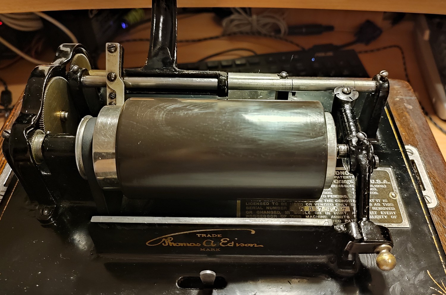
 An Edison Standard model B, SN #587857, manufactured circa 1908
2-minute gearing, end gate, tall case, model C reproducer, flat-style crank, reproduction horn.
As a foreword, you might have observed that I’m more a tinkerer than a collector, so the following article might be a blasphemy for all the hardcore antique afficionados. This particular piece is by no means a rare model; the 2-minute model B Standard was one of the most common cylinder phonographs. My estimation of the year of manufacture is around 1908, as this is still a single-gearing machine: owing to the high serial number and the fact that the 4-minute cylinders appeared in around 1908. From there on, machines could be then retrofitted with a 2/4-minute gear kit, whereas the models introduced later (such as D) had the 2/4-minute option straight from the factory.
 Perhaps one of the world’s first volume controls.
You no longer had to stick a sock in it to make it quieter 🙂
It came along with some parts, including mounting hardware for a crane horn, and two incomplete Recorders, one of them being an early Automatic (that I have sold off since), and one of a later model that I tried to make it working (below). The machine itself required just some lubrication and adjustments to the half-nut and bearings on top, to make it spin freely and quietly.
I did not bother doing a strip down-to-the-nub, since it runs good, it’s over a century old and especially pot metal can go from happy to snappy when least expected. Machining new replacement parts or rethreading some weird inch pattern in this metric part of the world, is something I wanted to avoid doing. You don’t fix what isn’t broken, in short.
Experiment 1: Electronic reproduction of 2-minute wax cylinders:
The very first thing was to record and digitize the cylinders I had in my collection. Of course, the simplest approach would be placing a microphone next to the reproducer horn, but this would also record the ambient noises and it would sound just as “tinny”, if not more, as the horn itself.
A better approach is to use a crystal (ceramic) pickup, also known as a piezoelectric transducer or “contact microphone”; these are commonly found as thin brass disks that convert vibration into an electric signal, and vice versa. Crystal transducers are found inside electronic buzzers, old phono pickups, some people use them to amplify acoustic instruments, and a piezo crystal is also used in lighters to provide a high-voltage spark when struck with enough force.
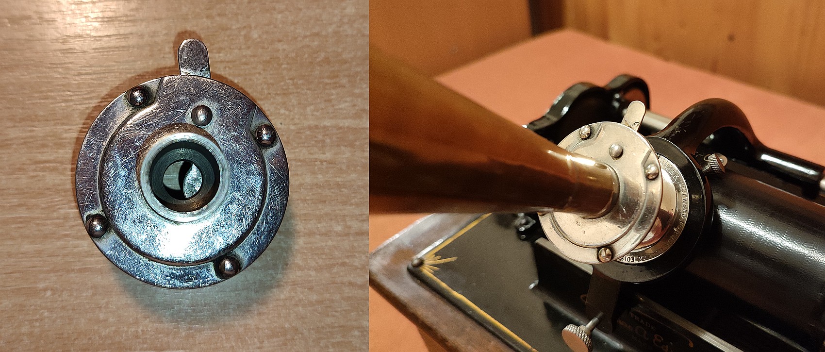
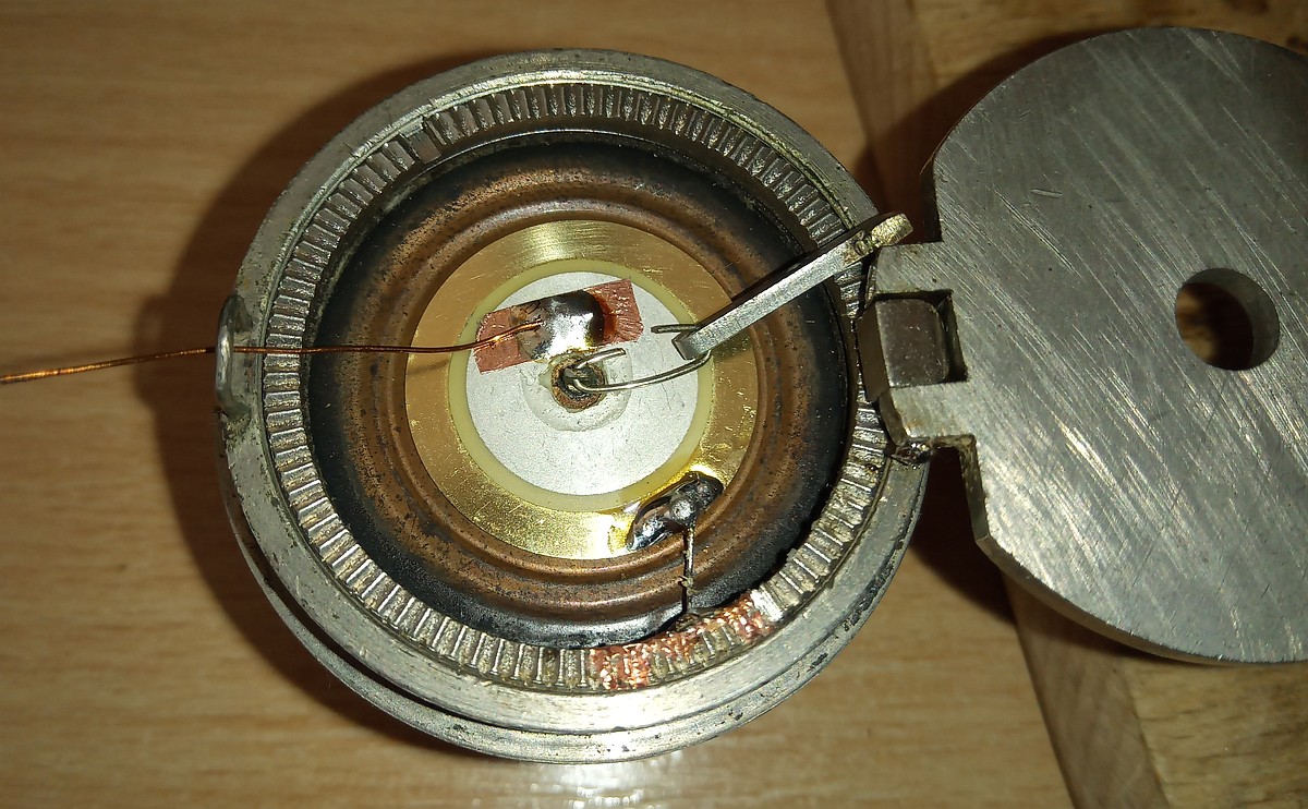 Crystal pickup mounted on the diaphragm of an Edison Model C reproducer
While at it, I have also put in new gaskets sandwiched in-between the copper diaphragm, as the old rubber ones were reduced to pieces. Remarkably though, the rubber legs on the bottom of the phonograph are still in good condition.
In the picture above, I have drilled a hole into the pickup for it to be able to fit onto the diaphragm, and sealed it around with epoxy to prevent cracking. The signal wire was passed through the “fishtail” of the reproducer’s weight, and the body was used as ground.
The output of a crystal pickup is high impedance, in megohms, so in order to connect this to a normal line level input, there needs to be some impedance matching involved. A sound input designed for instruments, such as a guitar pedal effect on a dry setting, or an old amplifier or tape recorder with ceramic phono input, or even a simple NPN emitter follower (or JFET buffer) circut will do the trick.
Connecting a pickup like this straight to a line level input will yield a weak signal, stripped off bass and treble – it will sound more “tinny” than the phonograph itself.
Playing a (very) moldy cylinder with a crystal pickup on the diaphragm
Now, touching the reproducer’s stylus with fingers on a setup like this, yields a similar, “bassy” BRRRRAP as if the same attempt were done with the stylus of a record player. This also means that it will amplify all imperfections of the cylinder (and resonances of the reproducer), that would otherwise be “drowned” if an acoustic playback were used.
The worst problem with this approach are the resonances, having the rigid pickup glued onto the vibrating diaphragm, especially during loud passages it sounds like clothes being torn in the most distorted, “metallic” way possible. Since this also affected the acoustic playback, this idea was scrapped. Perhaps if I had more than 1 reproducer, I’d put a bigger pickup between the gaskets, instead of the original diaphragm, and use it for electronic playback only.
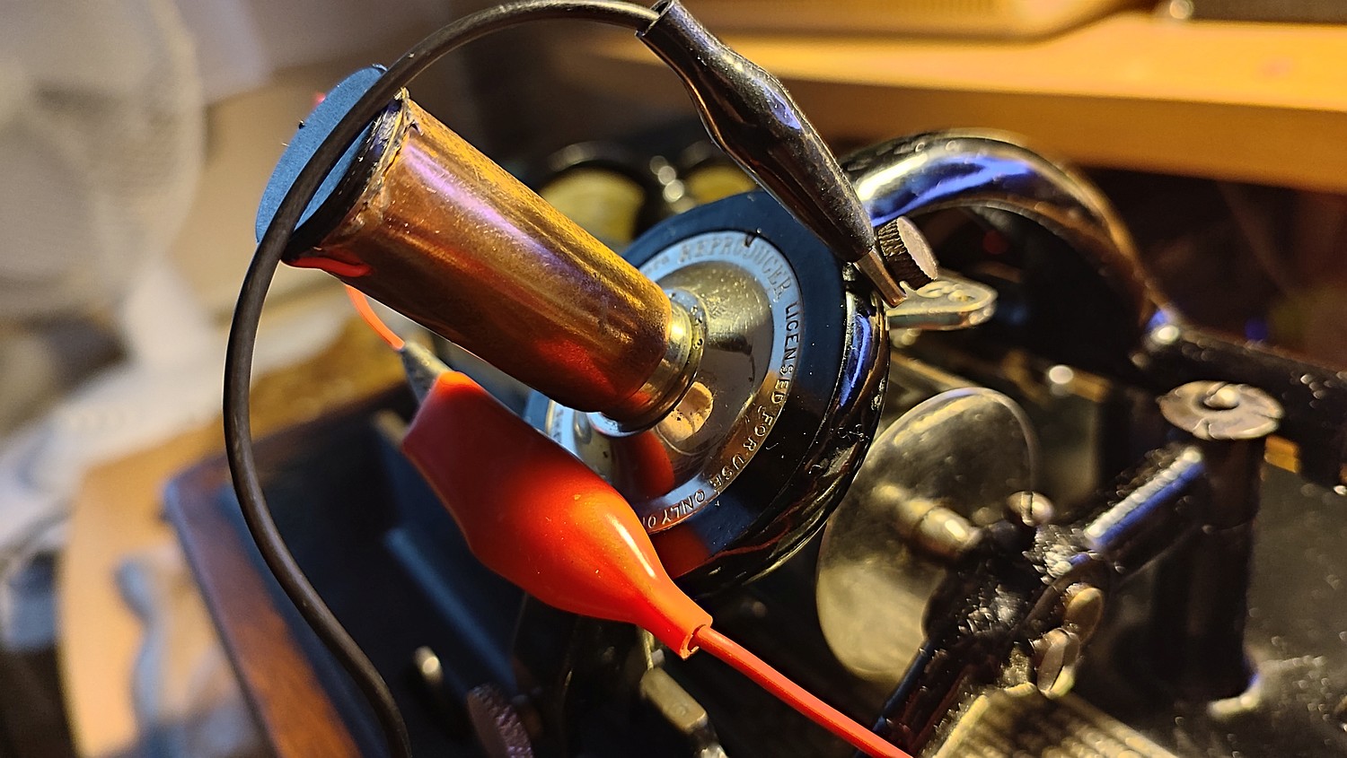 Putting the crystal pickup into a thin tube and onto the reproducer
An alternative, which I use today, does not modify the diaphragm of the reproducer, so the quality of the acoustic playback is unchanged. It involves putting a smaller diameter crystal pickup into one side of a tube, made from thin copper sheet metal, rolled to the same diameter for the horn adapter of the reproducer, for a snug fit. The connections are the same, with one signal wire only, and the body is used for ground.
This approach would not provide such a frequency response as in the solution above, however, the usable sound range of a wax cylinder is still between 300 to 3000 Hz, give or take. Also, more gain has to be used, amplifying any external loud noises close to the crystal pickup, but it is still far better (and less tinny) than using a horn and microphone.
In my wax cylinder recordings, I also apply a 4 kHz lowpass to filter out resonance of the thin C-linkage between diaphragm and the stylus rocker arm.
Experiment 2: Playing 4-minute celluloid records on a 2-minute-only machine:
4-minute cylinders came after 1908, first in harder black wax (Amberol) and later celluloid (Blue Amberol). Although they were recorded at the same speed as the conventional 2-minute “Gold Moulded” records, a different gearing and reproducer – with a thinner stylus – was needed to play these, since their grooves are narrower and more dense.
I only have a handful of 4-minute Blue Amberol cylinders, so just for a one-shot playback of these, to be digitized on a PC, I used an old record player tonearm:
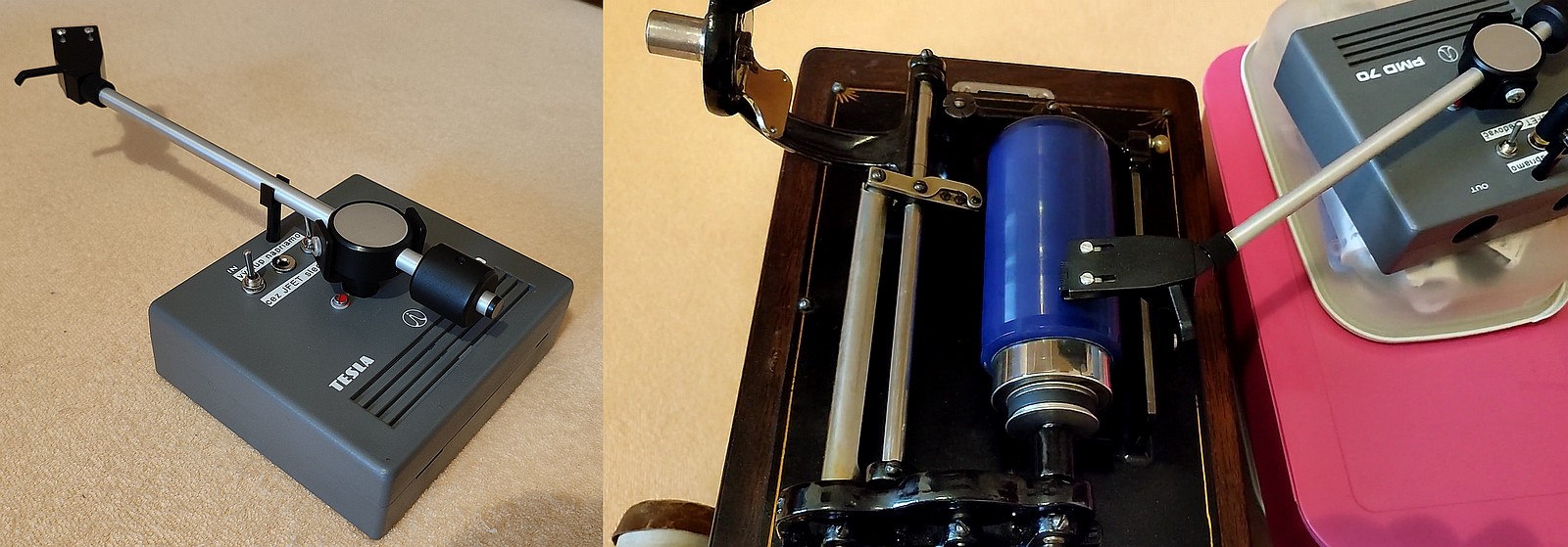 Playing 4-minute celluloid records with a record player tonearm (in action here)
Note that it is very easy to scratch the cylinder this way, the tonearm needs careful positioning during playback to keep it perpendicular, otherwise it can glide through and damage the cylinder (and the stylus too). It should also be placed from the other side, but this requires a disassembly of the reproducer carriage, since it stands in the way. It is also not possible to play the wax and (black) Amberol records this way, as the diamond tip will immediately dig into the wax and destroy the recording.
There is one advantage to this approach: it can be used to play shrunk Blue Amberols that no longer fit properly onto the mandrel, rendering the end unplayable with a normal reproducer. And even though cylinders are recorded vertically and not side-to-side like a disc, the sound of a record player pickup is incomparable to that of a horn.
Experiment 3: Recording blanks:
Whoo-whee, now it gets interesting!
I have mentioned above that the machine came with an incomplete recorder attachment, or a hollow body of it, to be precise. But before I could tinker a way on how to get it going, I needed to find out what to record on.
For “home recordings” at that time, a 2-minute Edison Recorder was designed to be used with a brown wax cylinder blank. These are of softer material than the later 2 minute “Gold Moulded” or even 4 minute “Amberol” wax records. So my experiment was to try and record on completely moldy and otherwise unplayable cylinders, in order not to ruin the historic value. Some people might cast their own wax cylinders using their secret recipe, but I did not want to go down that rabbit hole just for that.
To erase a wax recording, a “shaver” machine is normally required. Some early phonographs were equipped with a “shaver attachment” blade, but this didn’t catch on, perhaps due to low torque of the clockwork motor of the phonograph. Some people used the later “Dictaphone” shaver to create a blank, or perhaps put the cylinder on a lathe and some piece of sharp glass to trim it all in one go. However I had none of that, and I didn’t want to have a mess of wax shavings (“swarf”) everywhere…
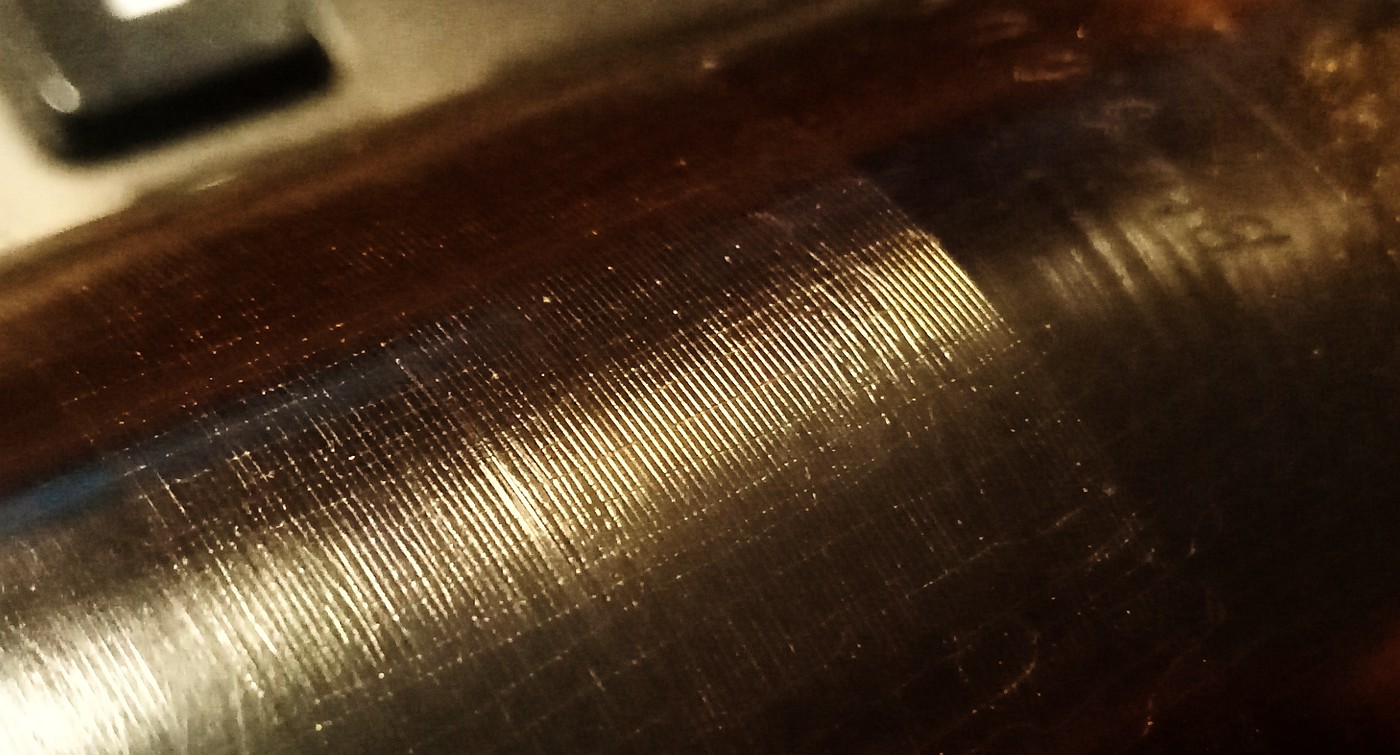
 Moldy “Gold Moulded” black wax cylinder after chemical erasing.
Rag marks clearly visible
And the simplest way on to erase a wax cylinder is to use a rag and a solvent. Out of the three I had within the reach of my hands – isopropyl alcohol, acetone and perchloroethylene – the last one was the only that did something. It does involve some rubbing action, being careful not to snap the cylinder, and it can be difficult to get rid of deep pits and gouging. Note that some strong solvents can cause the cylinder to develop hairline cracks during the treatment. If this happens, the cylinder will crack through eventually.
There’s one great advantage to this process: it won’t remove as much material from the cylinder, when compared to a mechanical “shaver”, and you won’t get wax “swarf” everywhere around. However, it is said that the noise floor is higher compared to a “shaved” blank – I cannot compare, and I don’t really care about that much.
Experiment 4: Acoustic recording:
As mentioned, I only had a hollow recorder body to start with. To get it done, I needed to supply a diaphragm, mounted on a thin gasket, and a cutting stylus with its holder.
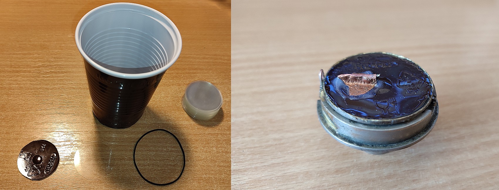 An improvised recorder: diaphragm cut out from a plastic coffee cup,
stylus made from a sharpened 1mm HSS drill bit, and crimped into its holder.
To get sensible recordings, a proper diaphragm material needs to be chosen first. This needs to be sufficiently thin, in order to vibrate with ease, but still rigid enough to resist deformation, as the stylus digs into the wax during recording. A cylinder record is vertical in nature, so the diaphragm needs to convert the sound waves into up-and-down movement.
Since the original recorders were fitted with glass or mica, a 33mm circular microscope sample glass, 0.1mm thick, obtained in bulk for a cheap price on a certain “Far Eastern” marketplace, was my first go. Needless to say, this yielded inferior results to polypropylene, cut out from a coffee cup that came from a vending machine. I presume a plastic diaphragm cut from a small speaker would work even better. Or perhaps aluminum from a beer can, a Beer-A-Phragm(TM). 🙂
For the diaphragm to vibrate freely, it needs to be glued onto a thin gasket inside the recorder. I cut a thin rubber belt out of an assorted collection to repair tape recorders, about 0.7mm in thickness. A suitable glue or sealant shall also be used around the outside rim of the recorder so that the air won’t escape, causing buzzing and resonances.
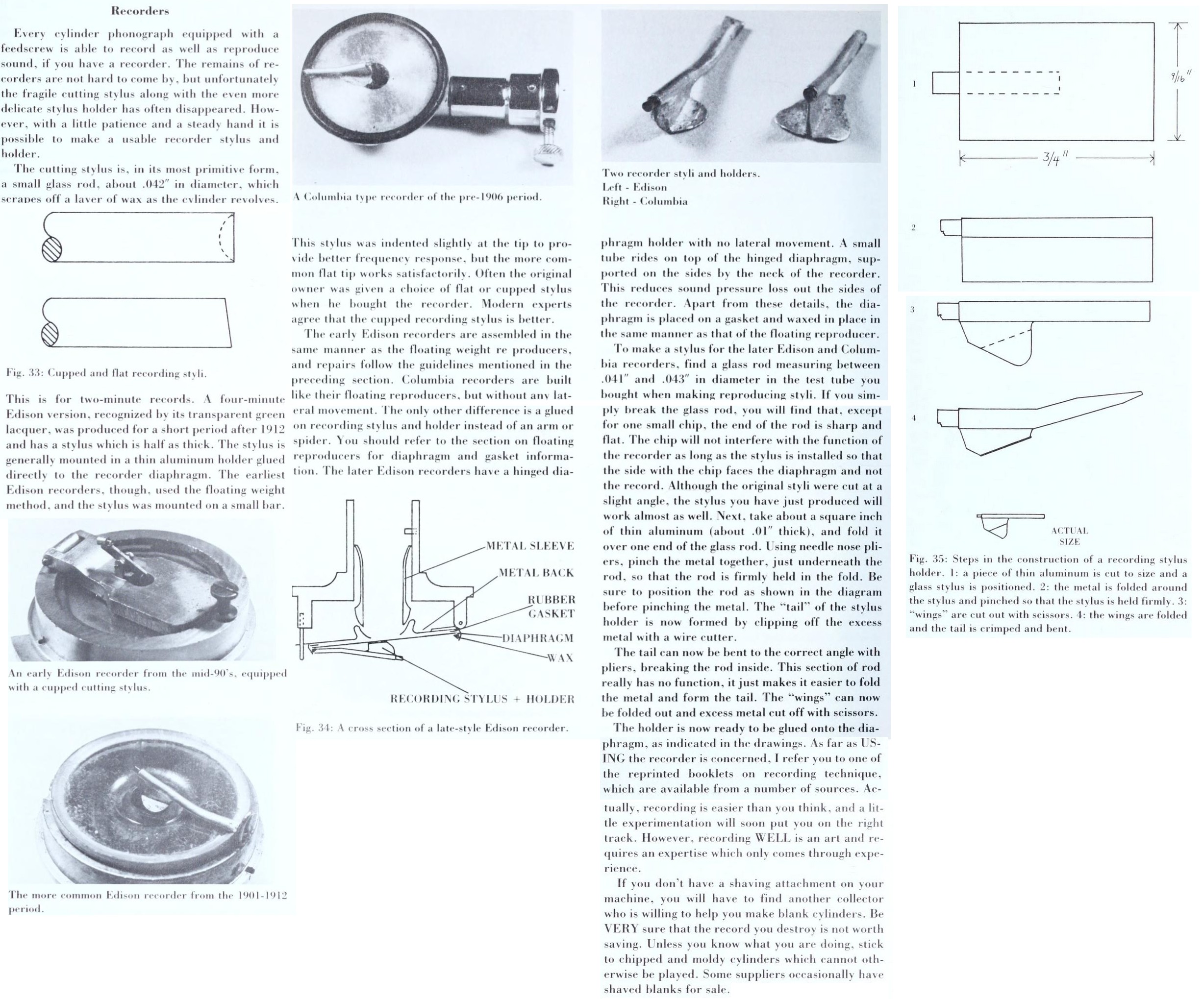 Notes on making a stylus and holder, scanned from The Compleat Talking Machine.
Now comes the most finicky part, and that’s the recording stylus. I’ve scanned a tutorial on how to make one from “The Compleat Talking Machine”, but the most crucial part is to set the cutting depth just right. If this is too deep, the cylinder will be gouged and unplayable, if too shallow, the recording will wear out after a couple of plays.
I did not have access to glass, nor had the know-how to draw thin glass rods, so I’ve used a broken 1mm HSS drill bit, sharpened on a rotary tool into a chisel shape. This has been then crimped into a makeshift stylus holder, made from a thin sheet of copper; the same I used to create the “tube” adapter for the playback pickup. It can also be aluminum from a beer can, or a different mounter, I used copper since I had a couple of sheets laying around and it’s easy to solder it, if required.
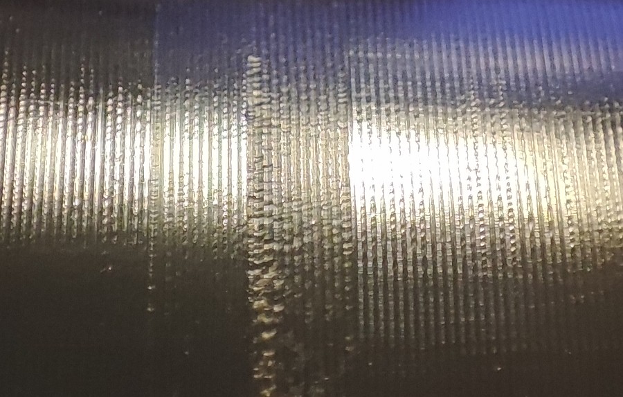 Recorder adjusted for brown wax was cutting too deep into a hard “Gold Moulded” cylinder
I used wood glue to mount and seal the diaphragm on the recorder, but I used a blob of hot glue to mount the stylus holder; and a hot air gun, to make minute adjustments to the cutting angle, completely via trial and error – until good enough.
Originally I have “calibrated” the recorder on a moldy brown wax cylinder, that has since cracked through after chemicallly erasing it multiple times. A brown wax cylinder is softer than a later “Gold Moulded” black wax cylinder, so I had to reduce the cutting depth to avoid pitting and gouging black wax cylinders, pictured above.
Before setting the cutting angle, height and the position of the stylus, you want to double-check that the weight of the recorder is free-floating from top to bottom. If it is not, or it “sticks” doing so, it will pit and destroy cylinders.
By the way, do not attempt to record onto later, 4-minute “Amberol” cylinders. These use a black wax formulation that is very hard – these will quickly dull out the cutting stylus, or crack during “shaving”, especially when done with chemicals. Also, 2-minute black “Indestructible” and 4-minute Blue Amberol cylinders are made of celluloid and cannot be used for recording this way.
All in all, when done properly, the playback horn on top of a recorder is usually enough to make a recording. For an acoustic recorder to be sensitive enough, so you do not need to shout into the horn, you need a diaphragm that vibrates easily, a very sharp stylus and a proper angle and position of it during recording. A quick check of that can be done by placing your lips on the recorder and “mooing” into it, whilst having your finger on the stylus: a strong, “electric”-like vibration of the tip must be felt. However, if the recording is too loud, the groove will be cut deeper and wider, causing “blasting” (distortion) and echoing on the next groove, as the stylus “hops” to the right.
Experiment 5: Electronic recording:
Put a speaker into the horn and you’re done. 🙂
With the relative success of the acoustic recorder, I have decided to skip actuating the cutting stylus from air pressure and convert an electrical signal to vibrations of the stylus directly, by using a bigger variant of the crystal pickup, avoiding the need for a sound diaphragm and gasket; allowing loud recordings of normal speaking, and even whispering, if wished.
For this experiment I have decided not to butcher the acoustic recorder, so I obtained a second, hollow recorder body for about 30 $ (the incomplete, non-working recorders can be found relatively cheaply), and tack-soldered the transducer directly onto the rim of the recorder:
 Electric vs. acoustic recorder attachments
Most of the recording predispositions mentioned above also apply here, including the requirement for the weight to be absolutely free-floating – for example, with the signal wire involved, a strain relief is required. However, in here, the transducer is not air-tightly mounted to the body of the recorder, allowing the thin transducer disk to vibrate on its own – the tack soldering was used only to connect the pickup ground to the body of the recorder.
By glueing or soldering the rim all the way, the crystal transducer would have to work and vibrate the whole recorder body like a speaker, rigidly mounted in the carriage arm, reducing vibrations to the stylus. A gasket could be used to mitigate this, however, soldering onto the body as done above, mitigates the problem of a second return wire. The recorder is made of nickel-plated brass, so a leaded solder bonds just fine after a bit of sanding.
Piezoelectric recording of music onto a black wax cylinder.
Notice how silent the actual recorder is at 0:30 when I turn off the internal monitor speaker.
A Tesla tape recorder was used for recording. Edison, Tesla, get it?
To drive the crystal transducer directly, I use an old Iron Curtain tape recorder made by Tesla in an amplifier configuration. This is because it contains an integrated ten watt PA made to drive a low impedance, 4-ohm load, from discrete NPN transistors, also with both channels fused, so it is very tolerant to abuse.
And abuse it is – a high impedance crystal pickup requires quite a voltage swing for loud cuts. This is achieved via driving the output of the PA to the secondary of a 9/230V mains transformer, so that the output voltage is around 85 volts peak at +0dB input level. Actually, the measured impedance of my transformer is around 5 ohms at a 1kHz sine signal, but it is still not constant as if a speaker were used. And yes, I did manage to blow one of the fuses, testing out the maximum output modulation, as the maximum collector current of one of the TO-3 NPNs were increased.
 This will record loud very easily
Anything over 100 volts peak (200 V pk-pk) and the recording starts to get distorted and “blasty” due to deep pits in the wax, so I usually keep the recording modulation within 40 to 80 volts. The maximum voltage before the crystal transducer cracks and arcs over after a length of time, is around 200 volts peak (400 V pk-pk), tested at 300 and 1000 Hz sine wave.
To further maximize recording volume, I usually apply a bandpass filter between 300 to 4000 Hz before recording, or just turn the bass and treble controls down – there’s no point of recording outside these ranges into a wax medium.
 Maximum recording modulation test
Once it starts looking like the surface of the moon, it’s time for a decrease
Experiment 6: Recording data on a wax cylinder:
I managed to boot a PC from a vinyl record, will I do the same with a phonograph cylinder? 🙂
With an “electric” means of recording and reproducing a cylinder, I have tried out if it is possible to record a simple datastream and decode it afterwards. The frequency response of a wax cylinder phonograph is similar to an old noisy landline with carbon microphones involved, so the experiment is to use the phonograph as a crude modem. Recording and decoding radioteletype and a datastream encoded in ASCII Bell 103, was a success:
 Hello World on an Edison wax cylinder (decoding in action here)
If you have a modem with an acoustic coupler (hardware or software), you should be able to decode the stream too
The process involved here was a software “minimodem” package running on Debian Linux, fed into the piezoelectric recorder and then decoded through a bass guitar EQ pedal, to convert the impedance required for a line level input of the sound card.
The higher speed protocols did not work reliably, such as with the 1200bps Bell 202, or old tape protocols, e.g. the Kansas City Standard or the IBM PC cassette (with a rate of around 1000 to 2000bps). For these to work, the signal bandwidth needs to be increased – for example, by experimenting with a second reproducer that has the crystal pickup in place of the acoustic diaphragm, using a sharp sapphire stylus on the recorder, or perhaps casting a different wax cylinder formula, and shaving it for a lower noise floor.
Then again, with CRC checks involved, you won’t fit a lot of data into 2 minutes… perhaps some Hello World app that executes and runs. But yeah, recording data works!
Experiment 7: Recording pictures onto a wax cylinder:
This made use of the “slow-scan television” (SSTV) protocol, widely employed through ham radio communications (shortwave especially) to send a 320×256 color bitmap picture:
 Left: reference picture of the Kriváň peak, right: best picture obtained from a wax cylinder recording (see here in action)
Experiment 8: Lateral recording:
Last but not least, this was the result of jerry-rigging an old phono pickup to the mains transformer wired to the tape recorder: before it arced over at around 250 volts peak, a record player stylus turned into a cutting head for a while, with the stylus vibrating side to side. Unfortunately, I had no means of playing this back again – being a constant depth recording, it only made noise on a vertical reproducer.
I did use the whole tonearm to play back celluloid records, but in case of a wax record like here, it would just pit and and scratch it deeply instead of playing. So it’s almost like a phonautograph – what we would ironically say nowadays, a “write only memory” 🙂
 Constant-depth lateral recording on a wax cylinder.
The hairline cracks were caused by exposure to organic solvent.