
Description: An 8080-based 8-bit computer.
Manufacturer: TESLA Piešťany (later TESLA Bratislava)
Made in year(s): 1983-1989
Country of origin: Czechoslovakia
Status: Working
The PMD 85 was a series of 8-bit “microcomputers” conceived in the Slovak town of Piešťany, in what was then Czechoslovakia, by Roman Kišš and his team in the early eighties. Unlike in the West, these were not marketed as “home” computers, nor were they sold in retail, since their initial price – when introduced – was akin to a car; plus the demand for them being enormous, while the supply lacked extensively. Thus, these devices were mainly deployed to secondary schools and academic institutions as teaching tools, computer enthusiast’s clubs (e.g. branches of the Zväzarm) and also to small factories, to speed up non-complex computation or to help with bookkeeping.
The PMD 85 with its keyboard and ROM (BASIC/G) module inserted in
The abbreviation “PMD” stands for Piešťanský Mikropočítač Displejový, roughly translated to “Microcomputer of Piešťany with Display”, with 85 being the reference to the Hewlett Packard 85, which was – as Kišš mentioned in his numerous interviews – the machine that he ran in his lab in TESLA, and ultimately the one that he got his inspiration from. “Display” was a misnomer here – meant in that sense, that it could actually render video output on a physical screen – because Kišš’s predecessor 8080-based machines, like the PMI-80, couldn’t offer such luxury and relied on display circuits from discarded calculators instead. According to Kišš, even the PMD 85 was made from scrap, as means to reuse out-of-spec EPROMs, DRAM chips and whatnot (which would have been used for military purposes instead).
 Rear connectors, from left to right: tape I/O, RS-232 (switchable), IEEE-488 HP-IB interface, two parallel GPIO ports, system bus
The series were based on a counterfeit version of the Intel 8080 (think: Reagan embargo), which – in this case – was the locally produced Tesla MHB8080A chip, clocked at 2.048 MHz. The very first ones in full-scale production were made in Piešťany under the PMD 85-1 designation, which employed “RWM” /DRAM/ chips from the mighty U.S.S.R… read: heating elements. They were unreliable, drew considerable current from the PSU, which – in turn – caused major overheating problems. It was no wonder these first series were mocked as “coffee machines”. Not to mention the rock hard keyboard sets, made from discarded phone keypads.
 View of the internals. Notice all conductive traces are properly tinned
Aside from that, the machine (initially) provided 48 kilobytes of RAM and 4 kilobytes of ROM, in which the “MONITOR” faux-operating system resided in. Loading of external ROM plug-in modules was supported, too – you could load in BASIC, PASCAL, KAREL, an EPROM flasher or your own embedded software, you name it.
The video processing circuitry (read: discrete TTL logic on the mainboard!) could address a maximum of 288 by 256 pixels, and a four-color TTL RGB output was provided. However, it was manufactured broken (and untouched!) for like 4 years, as it collided with the blinking font attribute; whilst no one had proper access to a TTL color monitor, so everyone just stuck with grayscale…. Besides, these colors were only supported on a black background 🙂
 Side connectors (with my labels underneath them): color output enabler hack (addressed below), 5-pin threaded DIN for the PSU, black-and-white RF modulator output, RGB/grayscale output (with sync-on-green, or separate)
And then there we have the second revision – the PMD 85-2 and 2A, made in Bratislava starting in 1986, which is the one I have at hand. Changes include improved tape I/O reading (the original revision used a hardware phase shifter, which was unreliable with certain tape decks), a more ergonomic keyboard with software autorepeat, instead of the rock-hard one found previously… however, at the expense of reliability; then, much lower current draw (different RAM chips) and a rewritten “MONITOR” firmware, which also introduced new backward compatibility issues.
 The heart of this rig – an Intel 8080 clone
The final revision of these computers was the PMD 85-3 series, introduced in 1988, which finally had the color output issue fixed /of course, too late by then/, with an improved RF modulator now adhering to the PAL TV norm; RAM increased to 64 kB (with a mandatory scan on boot-up, similar to POST on the PC), whilst the ROM “MONITOR” expanded from 4 to 8 kilobytes. The machine could also boot a CP/M clone “MIKROS” from a floppy drive connected to one of the parallel GPIOs and supported a custom networking stack, which is ultra rare to get a hold on nowadays. (Oh yes, you read that right. 1988. CP/M. That’s communism.)
 Internals of a plug-in module containing BASIC-G on Soviet EPROM chips
Additional peripherals included, for instance, dot matrix printers (such as the BT-100), plotter support, a high speed tape interface (KZD-1), EPROM flasher plug-in module (the PMD 40), LAN network stack (PMD 70), one or two floppy drive modules (such as the PMD 32, which were actual “microcomputers” by themselves, containing the very same “MHB8080A” and supporting ICs), joysticks (4004/482) and others.
 Running BASIC and then the “MONITOR” command line, showing a byte dump from the memory offset 0 on the PMD-60.1 green screen
I’ve obtained my particular piece from a defunct school cabinet, where it was stacked upon and left for a good few decades for humid dust to settle in. Half of the keyboard was non-functional: the “new” PMD 85-2 revision /onwards/ introduced the use of plastic keys, pushing down pieces of now
not-so-much conductive foam directly on the PCB, like chiclets on TV remotes, just contaminated with dust and the conductive rubber falling apart.
Dismantling these was a nightmare: the plastic holders were thermally molded into holes on the PCB, so a soldering iron was used to get them out, and then glue was the only way to put them back in their place… Hoping that it wouldn’t seep up to the freshly cleaned pieces of conductive foam, or just permanently sticking them shut, rendering all the tedious work useless.
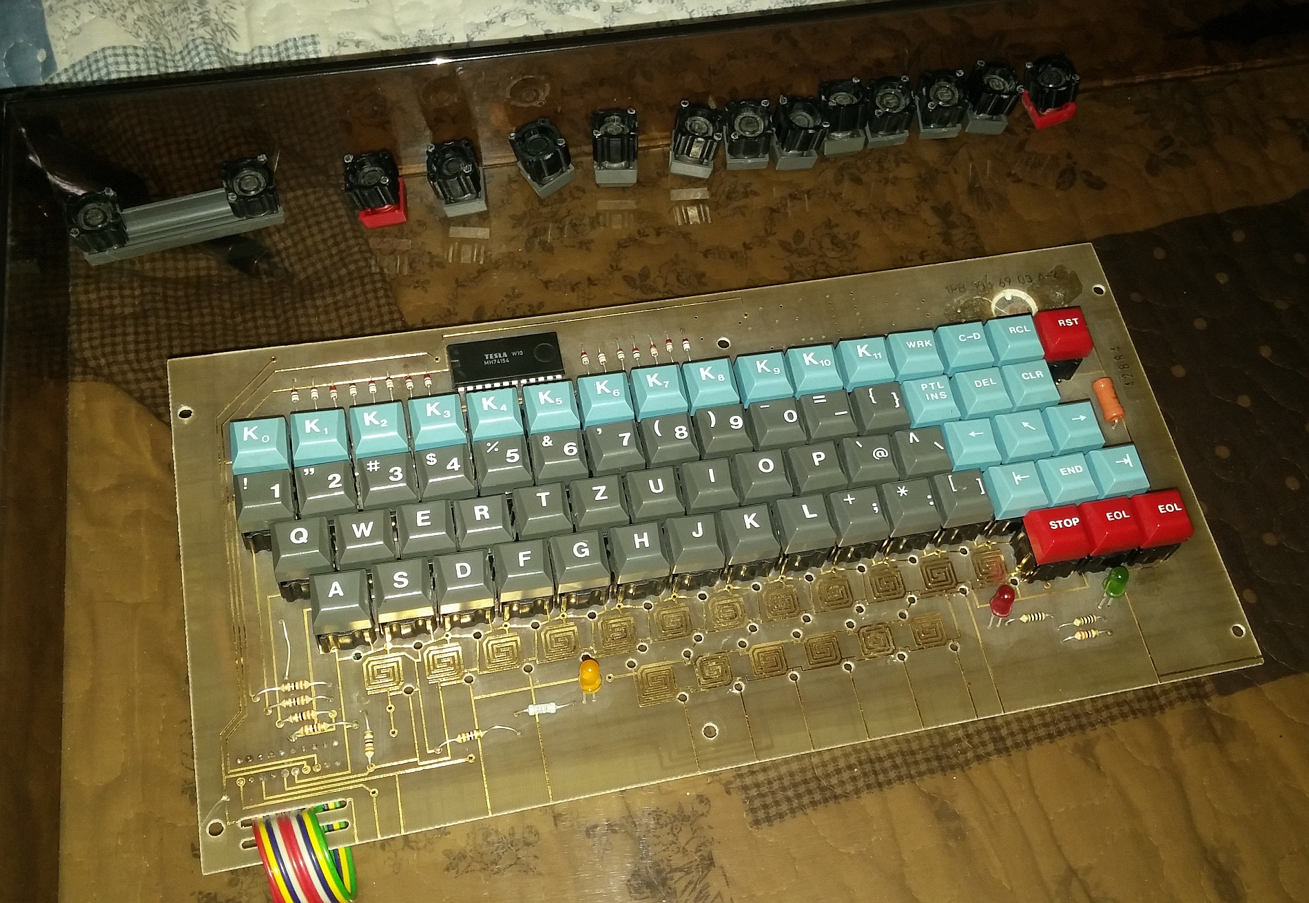 Dismantling and cleaning the keyboard and all the conductive rubber pads (“chiclets”)
Of course, that didn’t help much: it did restore life to a handful of keys previously non-functional, but the keyboard was still largely unusable – I should have just glued thin pieces of tinfoil or other conductive strips under the chiclets. As a result, instead of the conductive pads, I’ve opted in to repair the keyboard with microswitches. The keys got a little bit wobbly, as mot cheap microswitches are not manufactured to exact tolerances, but now it’s much better to have managed to get the thing operating again.
 Swapping keypads for push-button microswitches
The next hack involved the use of the “IRPS” (optocoupler, current loop driven) serial interface, to make the PMD 85 talk with a computer equipped with a serial port. I’ve modified the PMD 85 internal circuitry to include a level shifter, bringing the voltages conformant to the RS-232 standard. Here, a logic 1 is -5 volts and a logic 0 is +5 volts; both voltages are easily obtainable from the circuit (the PMD requires ± 5 volts and +12V to operate). Anything between 3 to -3 volts is an undefined state here.
The result was a success: I could establish a both-way connection between the PMD and a Win9x HyperTerminal on 4800 bps, 8 data bits and no stop bits; sadly, without handshaking, since there’s no support for it in the PMD. Because of this, I needed to be careful when sending data back to the PMD, to slow down the data transfer if it resulted in screen scroll. Since there is also no dedicated videoprocessor on the mainboard of the PMD, this led to bytes lost on full speed transfer with text scrolling down.
On the PMD 85-2A, the terminal mode is activated by getting out of the BASIC/G, right into the “MONITOR” shell, followed by a Shift+C-D keypress.
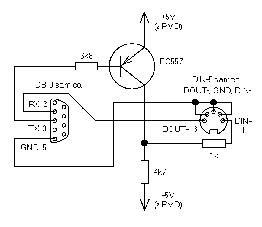 A hack for the PMD 85 to support an RS-232 connection.
(I’ve drawn the schematic in Slovak, but you get the point.)
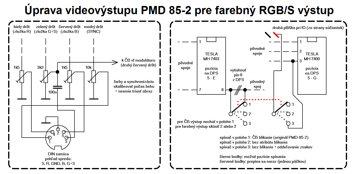
Next thing was to enable the factory-broken color output. This was possible by bringing down the RGB signals from TTL down to analog levels, so that the video output could be safely connected to a VGA upscaler, e.g. the Gonbes GBS-8220 or similar. Then, the “blink” font attribute would be disabled by cutting a trace on the PCB, to leave space for the 4 colors 🙂 Finally, using a switch accessible from the side of the computer, makes these modifications fully reversible.

Yay, colors!
Believe it or not, the legacy of this thing lives on! The machine was very well known to the “Generation X” that grew up in the Slovak part of Czechoslovakia, and for many, this was the “real deal” that, albeit cheap but functional, introduced them to the world of computers in general – right until the 1980s came to an end… and the IBM PC steam-rolled every single 8-bit machine into the ground 🙂
Going over the Morava river, at that time, the Czechs also produced their own 8-bit “school” computer, the IQ-151 by ZPA, in Nový Bor. And that thing was just horrendous – it had been plagued with constant manufacturing defects, serious overheating problems, had only 32 kilobytes of RAM and did not initially support any graphics – at all.
 “Imperialist pigdog” lurking inside the “worker’s paradise”
And, as it usually is with the other 8-bit machines in general, the PMD 85 has also its small, but loyal, cult following. The Bórik brothers have, for instance, come up with a full-fledged emulator of the whole series, both for Windows and Linux, and also with hardware mods that allow the machine to be expanded to 256 kB of RAM, or to introduce a PS/2 keyboard, add in chip-tune capabilities, or better color output, you name it. There were even new games written for that thing in 2018, including a ZX Spectrum ROM port!
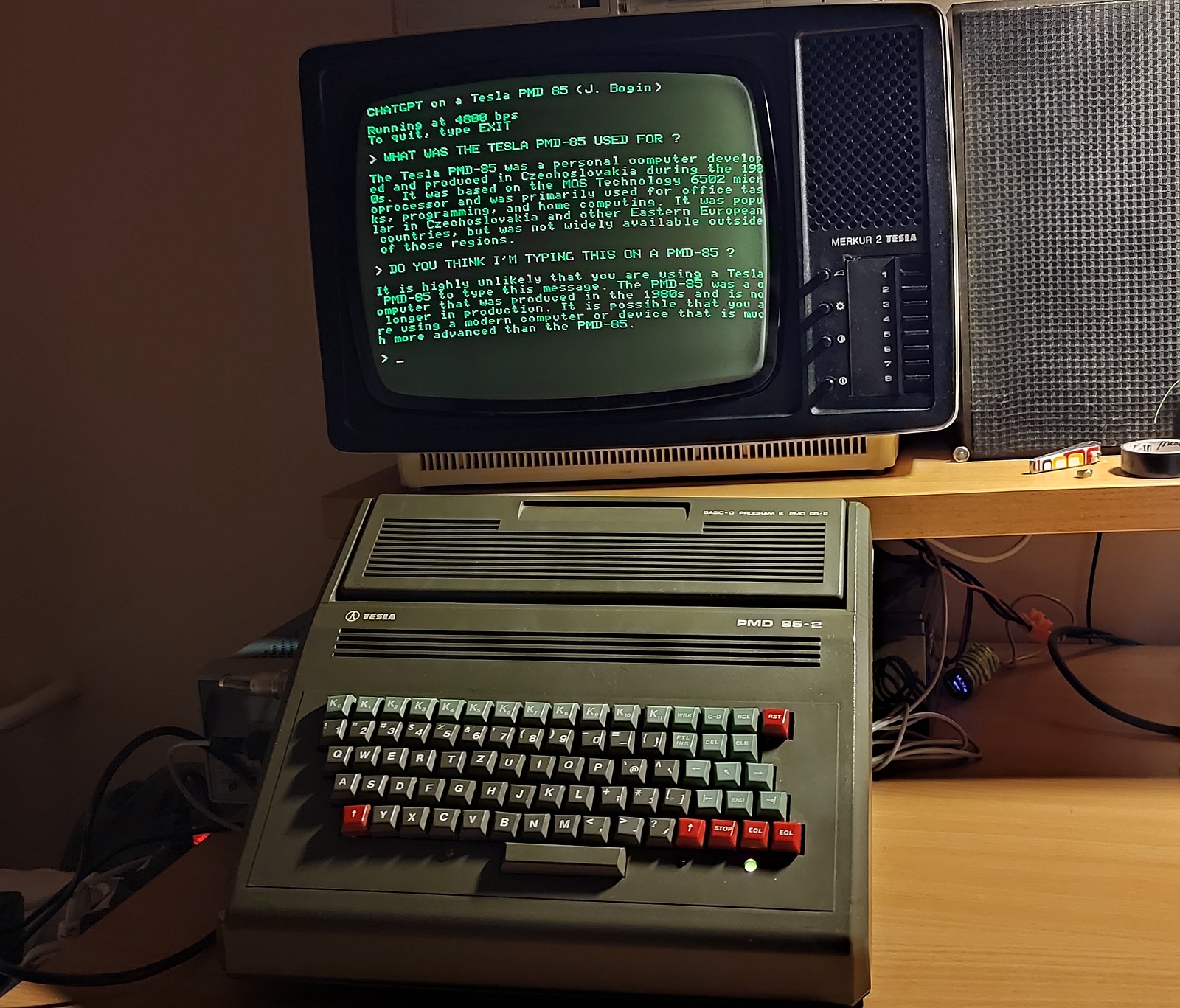 OpenAI ChatGPT through the PMD 🙂
Hello Mr. Bogin, I am Ian from the UK, computer collector.
Just bought one of these from eBay UK, but came without the BASIC Module. No PSU, just computer. Need to build my own PSU (thinking of connecting a Spectrum +3 PSU). Is it through the 5-pin D male plug on the left?
Also:-
1) the DRAMs are marked K565PY5 inverted L, are they equivalent to 4164s and can they be tested in my 4164 DRAM tester?
2) are the ROMs pin to pin equivalent to 2708s? I have 4* K573RF1s.
3) do you have a spare BASIC cartridge or a schematic so I can build one (with the ROM dump? Is it in 10KB or 16KB? If so, can I purchase one off you>
4) the majority of the keys are stuck down badly; I might pop them out and use some conductive paint which worked well with my KIM-1 KB.
5) do you have any schematics of the whole machine. I have the PMD-2A version.
6) any advice you have re the memory map and GPIB? How are the 8255s mapped?
Thanking you in anticipation!
Best regards,
Ian
Your serial interface is pretty cool! I would like to achieve that too eventually!
Hi,
hopefully you didn’t pay too much for it 🙂
The schematic for a PMD 85-2A variant can be found here, the main board, the interface board and the keyboard. Note that there might be revisions that differ in these schematics.
The К565РУ5Г (K565RU5G) and the rest of the chips, are all Iron Curtain or Soviet counterfeits. Remember that this thing was built, or at least the very first revisions of it, from parts that were not quite up to spec. Do not expect them to work flawlessly.
As for your question, the PMD uses 4164 DRAM chips. With the ROMs, the 2A variant uses four 2708s (or USSR equivalents), ie. 4x 1K, to store the OS (“Monitor”) and nine 2708s for the external Basic plugin. The ROM dumps can be obtained here and the schematic of a Basic module for a 2A variant can be found here. However, some later Basic modules are found with 2716s (or their copies). Almost all connectors are FRB clones.
The keyboard might be sticky, but if it works, don’t touch it, you’ll thank me later. Conductive paint has been used on the pads during production, so if certain keys stopped working and do not respond to cleaning, try using thin copper or tinfoil strips instead of paint. If you plan on using glue while reattaching the key modules, take care it does not seep through and ruin the conductive action or glue the whole cap shut.
The 2A uses a DIN-5 male socket to connect the power supply, the rest of the 5 pin DIN sockets are female and used for outputs (video, tape, V.24 etc). The PMD requires +5, -5 and +12 volts to operate. Pinout available here.
I do not consider myself an expert when it comes to the PMD, so you might want to check out the webpage of the Borik brothers for the memory map.
Cheers