
Description: A regenerative MW/LW AM radio receiver.
Manufacturer: various manufacturers
Made in year(s): 1938 to 1944, as far as originals go
Country of origin: Third Reich and its territories
Status: Working
The Germans are universally known, – given they have a free hand in what they do – for beer brewing, conquering other countries, their love for Ordnung, and overengineering stuff. But let’s not generalize – the latter is not always true, especially if there’s some kind of outside pressure that results in their socks getting soggy. A nice example to this exception of a rule, is the DKE “German Small Receiver”, or Deutscher Kleinempfänger, if you prefer.
Behold the bakelite
Originally conceived in 1938 by the orders of Reichsminister Dr. Goebbels as a propaganda tool, these cheap radios were intended so that each and every German family could listen to the Führer, at that time being pumped in hundreds of kilowatts of RF power through all the long- and medium-wave spectrums of the Reich. The radios had a price tag of a laborer’s 1-week-pay and were sometimes distributed for free.
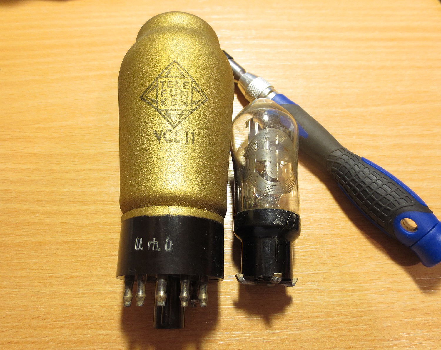
As such, the DKE is a 2-tube regenerative AM receiver, employing a VY2 half-wave rectifier, and a VCL11 combined triode-tetrode as a detector and to drive the speaker. These 2 vacuum tubes were specifically engineered in 1938 to be used in the production of the DKE: their combined series heater voltage was 120 volts, to be heated straight from the 120 volt mains, and through an internal dropping resistor on 150 and 220 volt mains, acting as a voltage selector.
Since the design of the DKE is transformerless, the radio can run on a DC power too, the whole chassis of the radio is at mains voltage, the anode (B+) voltage depends on the value of (rectified) mains voltage, and there is no output transformer for the speaker: the VCL11 drives the high-impedance,
17’000 ohm metal-reed-speaker directly, like an earphone.
 Back view, without the paper cover
The radio was made entirely of bakelite, hardened cardboard and “Pertinax”, which is paper bonded with a phenol-formaldehyde resin; nowadays known as the “FR2 board”. Metal was only used where absolutely necessary: the permanent magnet of the speaker, wiring, screws, rivets, point-to-point contacts, a small sheet-metal shielding piece for the triode – and that’s it, the rest is paper and plastic. Even the rear speaker box was made from cardboard.
Put into mandatory production for all German companies that were producing consumer electronics, as time went on, the receiver was also manufactured in cities of occupied countries, as in Prague or Warsaw. The manufacturers themselves were not allowed to modify the design or the electronic circuit; they could only print their logo on the paper back cover and put their stamp on the circuit board.
 Schematic of the Sparmodell 1940 variant (courtesy of IMPERATORREX.DE)
All in all, there were 3 basic variants of the circuit: the original DKE 1938, followed by 1940 and then 1944. The later 2 “Sparmodell” (cost-saving) variants, were called just “Deutscher Kleinempfänger” (without the 1938) on the back cover. They started to omit the rear “Entbrummer” (“de-humming”) trimpot to adjust the tetrode bias (and thus, current draw), replacing it with a fixed value resistor. Then, cardboard “ears” were used to mount the speaker, instead of metal tabs. The last 1944 variants used a resistor in place of a filter choke of the CLC mains filter stage.
After the war, the DKE was de-Nazified, renamed and continued production until about 1950; some variants were also equipped with shortwave.
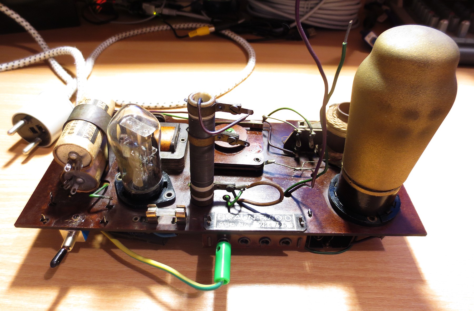 The point-to-point chassis, mounted on a paper-formaldehyde FR2 board
My particular piece is by no means an expensive, highly-sought-after piece: despite the electronics almost not being touched, the radio lacked the original cardboard back cover, the mains plug was gone, the original power cord left a lot to be desired and the paper power switch was received completely snapped. Ah well. At least the front emblem with the Reichschicken survived the other’s futile attempts of forgetting the history 🙂
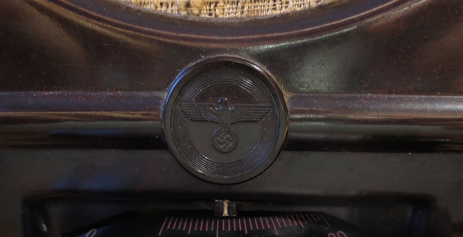 What time is it? It’s Reich past nein!
Since the receiver was incomplete, it didn’t hurt to put a few new (old stock) parts in. As such, another textile power cord was used in place of the one that crumbled onto itself; this time, with a grounding plug – the radio does not receive much of a signal without a solid ground anyway.
 Backside replica made from paper and cardboard
The old “Hydrawerk” electrolytic capacitors were kept in, but disconnected and new 3M3 electrolytics were used at the bottom of the circuit board. This is because the small piece of sheet metal that holds these 2 caps in place, also crimps the mains power cord in place. But technically, you could still attempt to “form” (rejuvenate) the old electrolytics with some rectified mains and a high-value resistor, charging them up with some 0.5mA of current slowly over time… I did not bother. Kept them in, though.
One needs to take care here: the capacitors shall not have a capacity of more than 6 microfarads, otherwise the anode voltage of the VCL11 in-load will rise above the maximum value of 250 volts (on 230V AC), and induce parasitic oscillations and other woes.
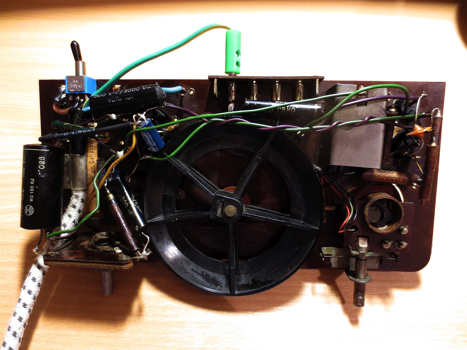 The other side of the circuit board.
The 4nF coupling cap (next to the triode shield) was replaced shortly thereafter.
The VY2 rectifier had also decreased cathode emissions, so I’ve kept it in the socket for good measure, masked its bottom pins and used a solid-state rectifier hidden on the bottom of the socket, with a 680 ohm resistor in series with the VCL11 heater to make it work. This increased VCL11’s anode voltage from +98V to +240V (after heating up and current draw); still within spec of the VCL11. However, a leaky 4nF coupling capacitor next to the triode section was responsible for increased mains hum – swapped it for a modern 4n7 cap.
Then, the 300 ohm “Entbrummung” trimpot/resistor was brought down to 220 ohms to set the tetrode bias to a current draw of some 15-20 mA (shall be 15mA at +190V, according to the schematic). Since the receiver is mains-fed and half-wave rectified, there’s always going to be some faint hum on AC power; to decrease it further, one suggests using direct current to heat the VCL tube, or DC power altogether. Mains sockets with DC were actually still a reality of the 1930s, especially in rural areas, that were dynamo-powered.
 VCL11 with metallic powdered-oxide as shielding, VY2 diode with the reichschicken
Now, the radio might have had earned the nickname of “Goebbelsschnauze”, or the “Goebbels’ snout” during the 1940s, however, Herr Goebbels has been off the air for quite some time now, and so – it might have been true that the radio was good only to listen to strong stations back in the day. Nowadays, medium-wave and long-wave AM transmitters are more scarce, and the thing can be used to pick up more distant stations than having the omnipresent F¨uhrer scattered all around the MW/LW bands. With a solid ground and some longwire antenna, indoor even, I have been able to pick up Arabic programming, BBC, Russia, Spanish stations, Deutsche Welle, and of course Poland, Czech programming and Hungary, close to my location in Slovakia. On a 5 meter-long-wire wrapped around radiator pipes, the Czech transmitter is so strong that it sputters all over the LW band, with the antenna plugged in to the top of the coil (see schematic above).
 HYDRAWERK, a company that makes capacitors for the benefit of the Nazi hydra
Of course, it’s not a superheterodyne. Being a TRF radio, it does not have a volume control – the volume depends on the signal strength you’re receiving, and as such – the radio needs a long wire antenna and a ground to operate properly, and its tuning is very touchy-feely.
To tune this radio, it’s best to have the antenna coil air-coupled tightly with the LC tank circuit of the detector by rotating the left knob all the way to the right (unless the stations are talking through each other), for a crude “volume control”/sensitivity reducer. Then, during the tuning, it’s good to have the regeneration/positive feedback (right knob) tuned somewhere in the middle, so you can hear the AM carriers whistling while turning the dial. A station is then tuned “just right” with the tuning dial when the AM carrier turns from whistling into low-frequency rumbling. Disengaging the regeneration by slightly rotating to the left, until it stops growling, gives the “loudest” volume.
A very important thing is to not have the regeneration turned all the way to the maximum: the tuning capacitors (made from hardened paper) can be a little degraded, so with too much feedback (and/or anode voltage), the receiver can start oscillating, emitting an ear-splitting squeal. Yes, the oversized earphone turned speaker CAN be loud 🙂
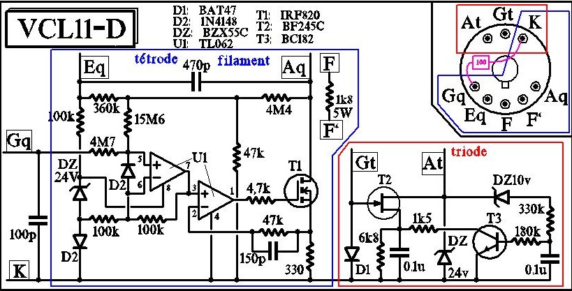
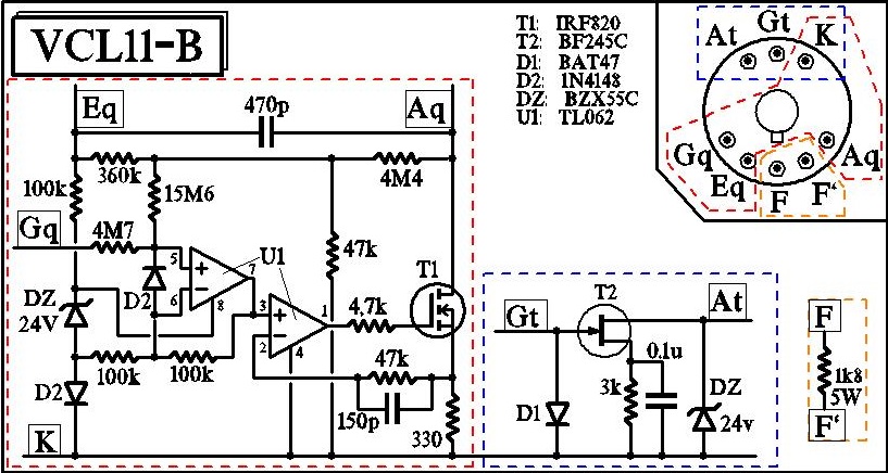
Last, but not least: since the VCL11 tubes are hard to find now (as they have originally been developed for the DKE), UCL11’s can be used in place, if the heater resistor and the biasing is appropriately modified.
There’s a solid-state drop-in replacement for the VCL11 altogether, see circuit here (alternate variant here) as an example. Note that the tetrode bias resistor (the “Entbrummer”) will most likely have to be bypassed, the output MOSFET needs to be heatsinked, and be sure the circuit is completely shielded – otherwise it will hum or shriek like mad. However, make sure the shielding (which is on mains potential) does not make contact with the heatsink (MOSFET drain) unless properly insulated.
The resistor between f-f if can be omitted, if there is a solid-state rectifier in place.
Sir; Would you have any idea where to find a replacement speaker for the deutscher kleinempfanger?