If you have a sweet spot in vacuum tubes, used in vintage electronics, you might have seen a special kind of a tube that was used in many pre-war AM radios as an indicator of signal strength, thus, proper tuning. And with a simple circuit like this one, you can make it bounce to the rhythm of your music!
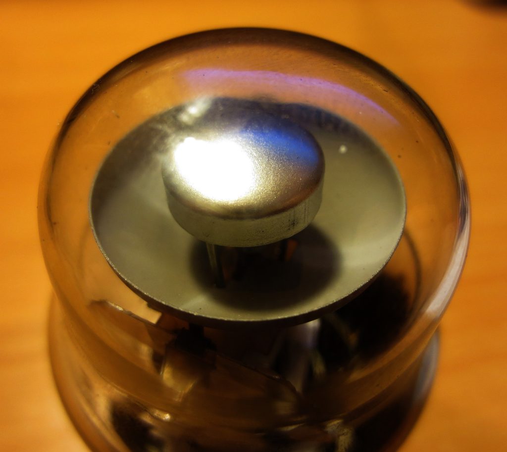
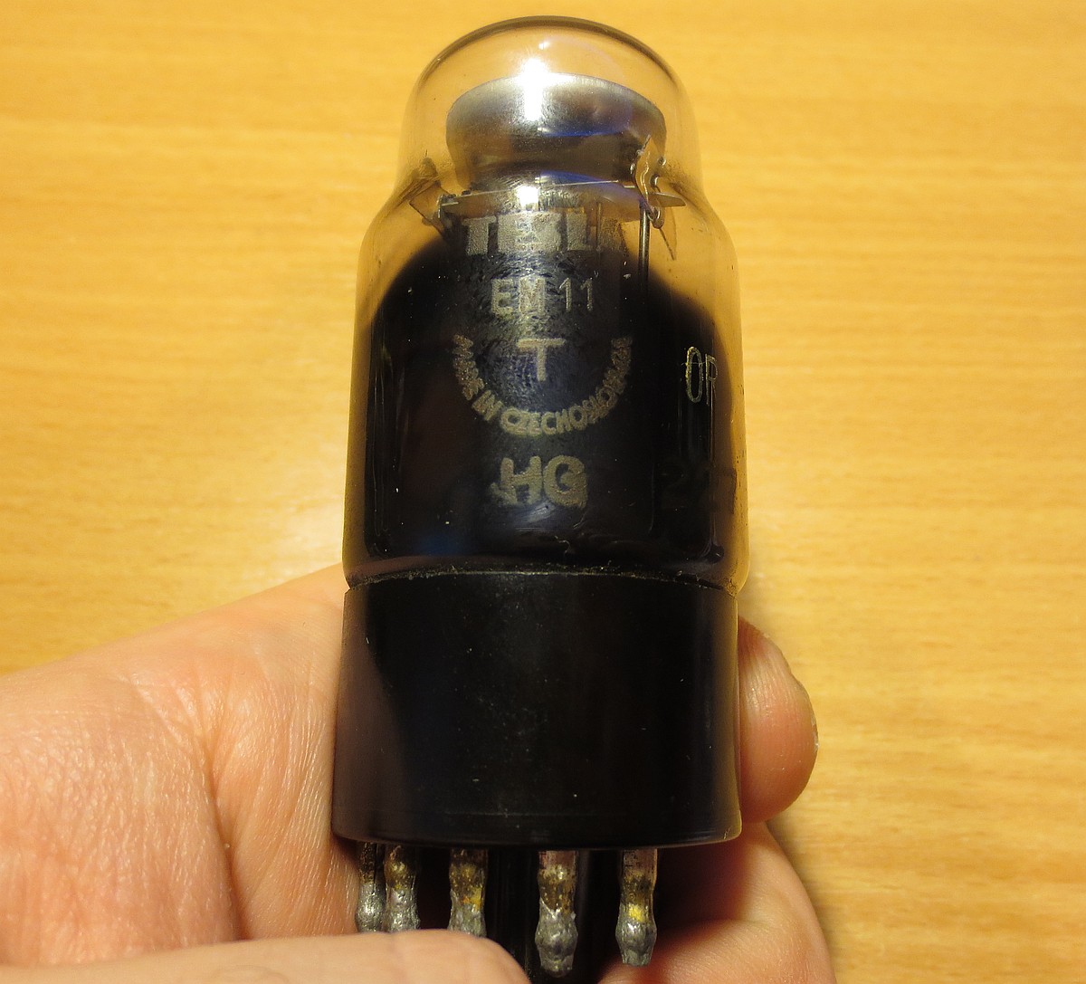 EM11 (6U5G) tube, post-war production, made by Czechoslovak Tesla.
‘Footless’ base (German Y8A)
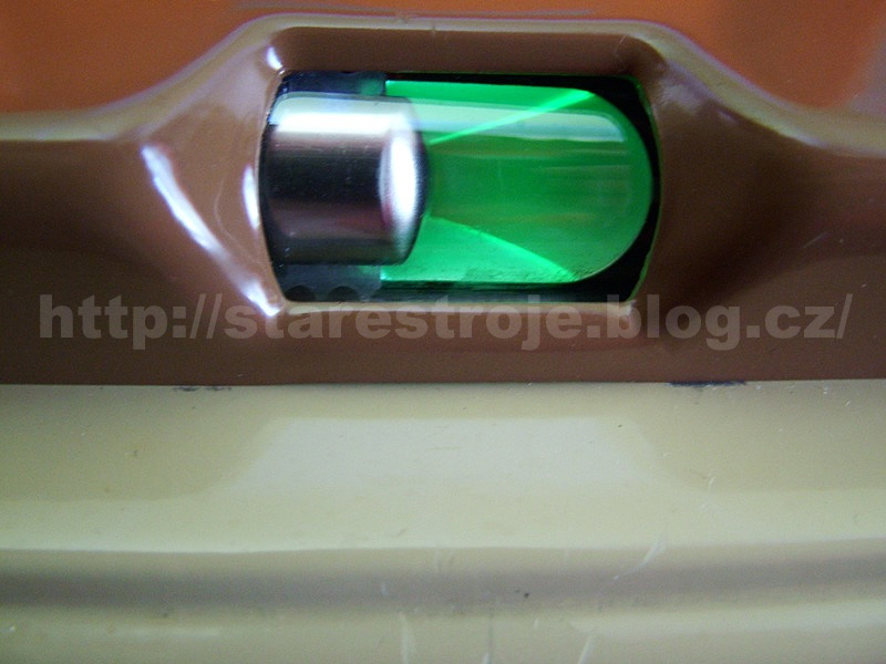
Firstly, how does this design work? Well, it’s a special kind of a miniature CRT, with a small parabolic screen coated with a green-emitting phosphor (ZnS, for example), held at anode potential. As soon as the cathode begins its thermionic emission of electrons, a green glow of the phosphor can be observed at the viewing end. In an idle state, only four narrow circular sectors will be seen, because a control electrode (the grid) is repelling electrons from the target screen. By gradually decreasing the negative charge of the grid (as the signal strength increased), with respect to ground, the green sectors get larger, eventually completing the full circle. And as the very first vacuum tubes of this design were mounted in a way, so that their screen was facing the radio listener, their trademark name of a ‘magic eye’ got coined.
After WWII, magic eye tubes were, besides radios, also used as an (actually) cheaper alternative to needle-based VU meters in consumer-grade tape recorders of the 1950s and 1960s. Also, new designs were produced, such as the EM84 tube, which had a vertical bar screen, instead of a circular design, but the ‘magic eye’ designation stuck to them too.
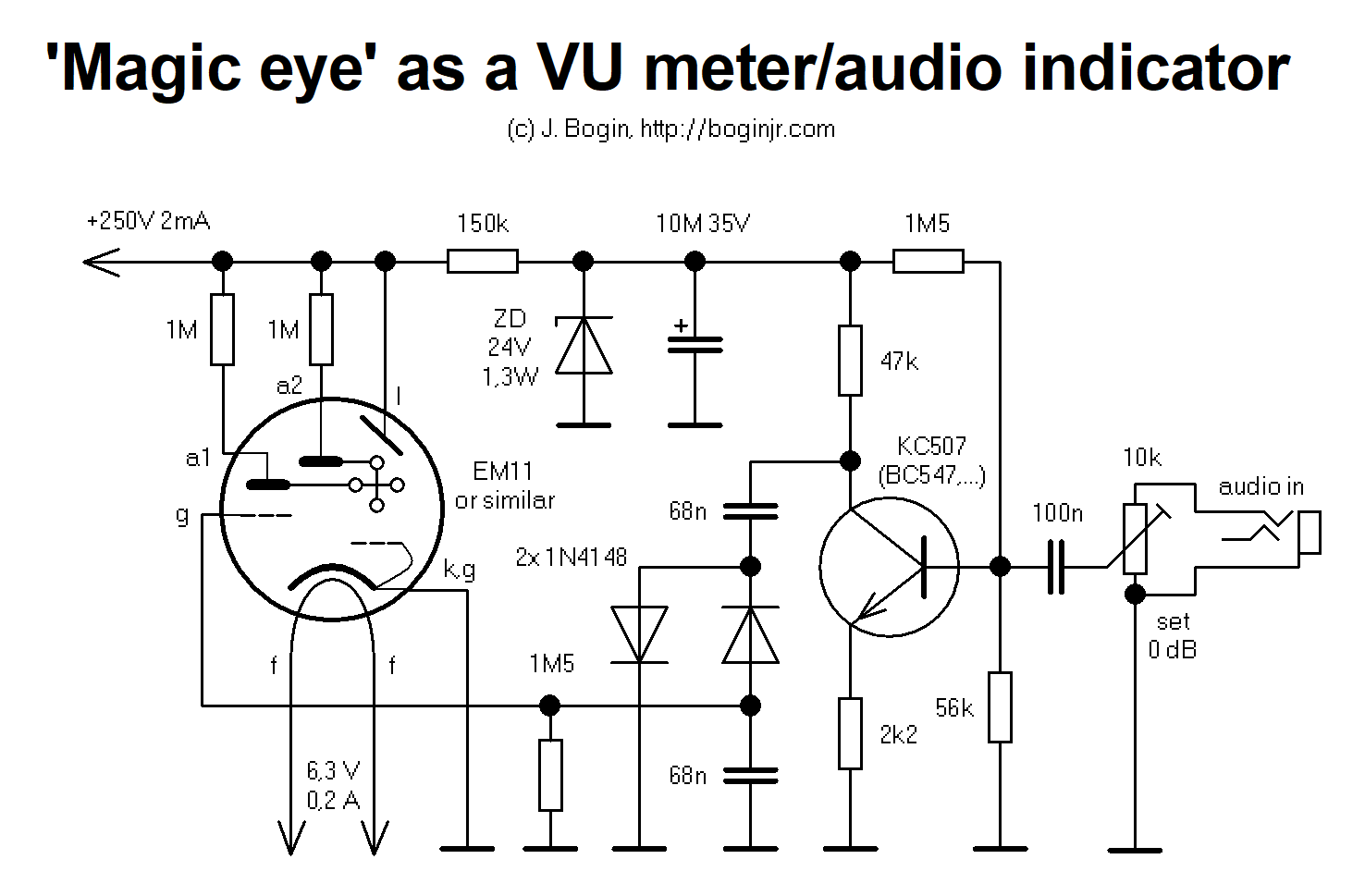 Schematic (click to enlarge)
 EM11 in operation. The whole circuit, excluding the power supply, fit directly beneath the prehistoric Y8A base.
The operation of this circuit is quite straightforward and can be used with other tuning indicator tubes in general. There’s an anode supply of 250 volts d.c., functioning also as a voltage source for the grid (current limited and stabilized to 24 volts, by means of a small Zener diode). A simple transistor amplifier in a common-emitter configuration, converts the input audio signal to a negative voltage swing between -4 to -20 volts, required for the control grid. You want to tune the trimpot so that there’s -20 volts with respect to ground at 0 decibels (maximum volume) of your audio input; and a maximum of 0 to -4 volts in silence. If you’re using a different magic eye tube, pay attention to the different pinout and perhaps use a slightly different anode (plate) resistor – the recommended values can be found in a particular datasheet of your tube. The screen can be held at full potential without current limiting, as no current flows from there.
The anode supply voltage is not that crucial, as a properly functioning indicator tube should light up, starting at 100 or 150 volts or so, depending on the status of your cathode emission and the ‘health’ of the phosphor coating.
EM11 in full swing of the control grid voltage
As you can see, current draw is really minuscule, so if you don’t have a mains transformer that puts out something around 250 volts after rectification, you can ramp its voltage up by means of a simple half wave multiplier. You can also use suitable small mains transformers from “wall warts” connected back-to-back, like, say 230/6 volt transformer secondary connected to a 9/230V transformer. Or you can build yourself a small flyback inverter.
The circuit will also happily run from a voltage divider straight off rectified mains 230V~, but I do not endorse this, as there will be a nasty surprise waiting for you at the audio input jack, as the common return point can become a live wire, giving you a mighty handshake, perhaps a lesson in breakdance. Also, devices equipped with audio jacks have to withstand short circuits, while the jack male is inserted in. In this case, if you attempt to plug in an audio source with its ground potential connected to mains ground, the jack will be blown to smithereens, until the circuit breaker ends the show 🙂
 EM11 screen. Notice the phosphor burn-in, due to prolonged wear.
An obnoxious problem with these vacuum tubes is their degradation in brightness. This can be caused by cathode poisoning, which reduces the emission of electrons. If this is the case, you can “rejuvenate” the tube by applying the heater up to its nominal voltage, and then, slowly and gradually, you increase the filament voltage up to two (or even two and a half) times rated voltage – and keep it there for a few minutes. Anode supply stays off the whole time. Note that this is just a temporary solution, plus if you don’t do it slowly, you risk rupturing the filament, rendering the tube useless.
A second case is the phosphor being just flat worn out, due to burn in (pictured above), or that it had been subjected to visible and UV light for too long, which degrades its luminiscence. Just like a CRT screen. This cannot be helped – the only thing you can do is to raise the filament voltage, which also increases cathode emission. While you’re at it, you can also ramp up the plate voltage, even up to 500 volts if you wish. Of course, this shortens the lifespan of the tube rapidly, but it will be eventually rendered useless after some time, one way or another. So if you’ve got nothing to lose, try it. Remember that these vacuum tubes were a consumable in their era, and just like a classic lightbulb, each vacuum tube is destined to wear out and fail 🙂
I just found that I have a 1629 in a box of tube I picked up and a circuit like this would be a perfect use for it!
Thanks for your good article!
This is quite cool! I’m actually working on a project right now and decided I wanted to convert the the existing 6G5 into a VU meter… It’s not so easy to find info on doing that!!!! I wish I had more experience with the magic eye tubes… But between this and my experimenting, I feel like I should be able to do it. Thanks for this!!! ,Tim
Also, looking at your schematic, the filter cap says “10M 35V” I’m assuming it’s 10 Mf/uF, right?
Hi,
Here.
thanks for the circuit , its work well
can you design a simple one layer PCB?
Hi Bogan Jr., I’ve just made a magic eye display as a nice VU indicator for my project, a simple 4-inputs in audio selector, with the output going to the amplifier. I’ve connected the signal in-to-magic eye wires to the outputs of my project, which then go off to the inputs of the amplifier.
I’ve found that with the magic eye turned off, the sound is fine. On though, the sound is quite static-like. Is there some kind of isolation I should do, do you think? Or is the voltage level from the tubes affecting and distorting the sound going to the amplifier?
I’d appreciate any thoughts you might have!
thanks for your good article
Barney
FIrst check: be sure your tube’s anode supply is galvanically isolated from mains, e.g. by using an appropriate transformer. If that does not help, try a 1:1 transformer for the signal input. Also, take care you don’t have any ground loops in your project.