Apart from flyback transformers or MOTs, automotive ignition coils are also used as high voltage sources by many enthusiasts. Especially those classic cylinder-shaped ones, used in carbureted engines pre-1990, since these were driven directly from the battery (through contact breakers) to generate sparks and a sturdy primary/secondary winding with appropriate insulation had to be met.
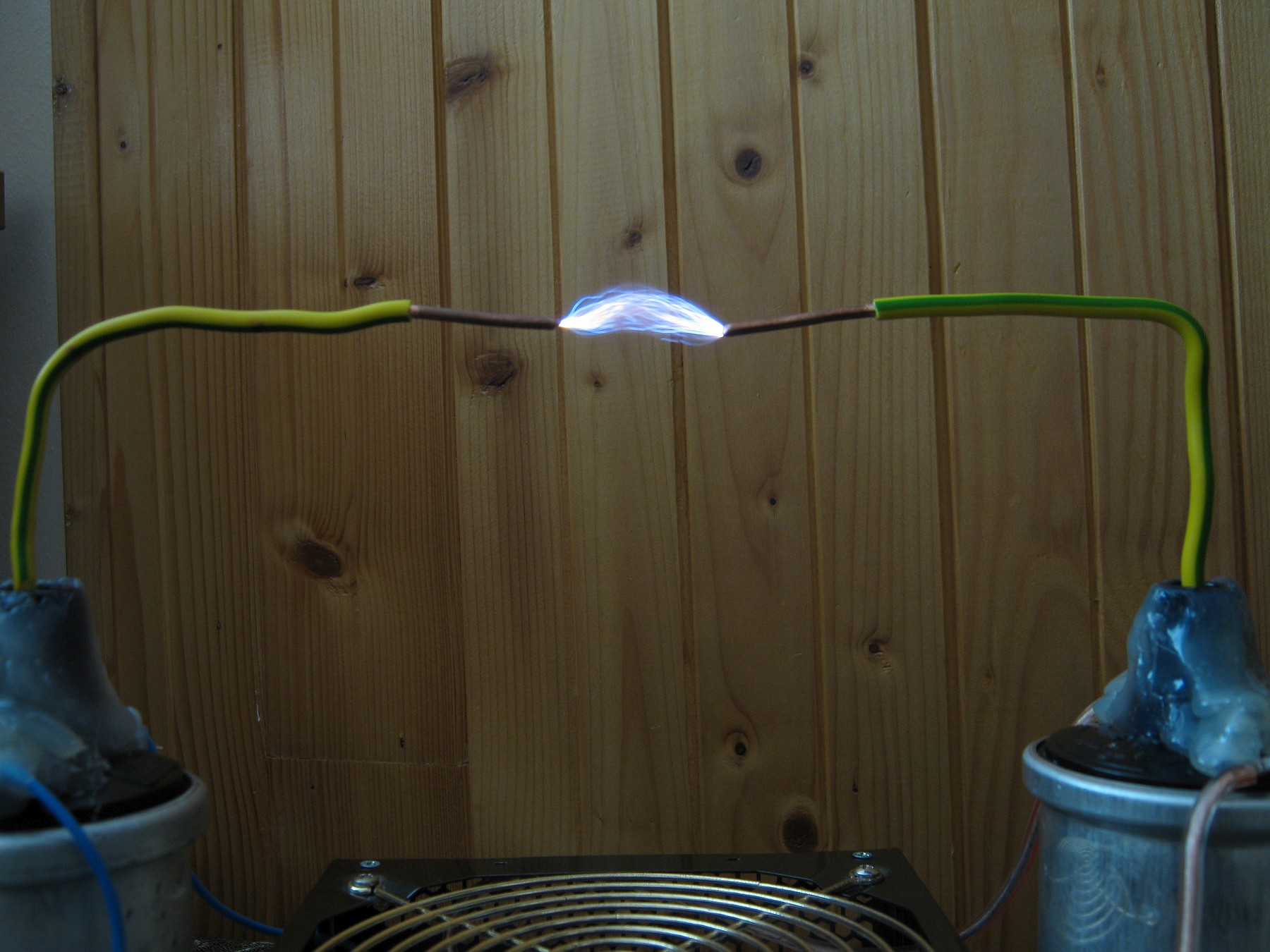
 7.5cm sparks (50 kV)
Now, whether you have the old one or today’s modern coils, the principle stays the same. Any ignition coil is basically a special iron-cored transformer with an open magnetic loop and a high sec/pri turns ratio, with its HV return pin permanently connected to the primary. This setup is then submerged in oil, or dipped in any similar insulation material, like asphalt or concrete – and hermetically sealed.
Most ignition coils as of today are way smaller, since these are driven through your car’s electronic ignition system. For experimentation however, I recommend the former type.
 3.5cm arc-like sparks (30 kV)
My approach how to drive these two (came from a SKODA 120) was in anti-parallel through a mains sine-wave chopper, like a light dimmer, similar to my triac phase regulator circuit. To chop the waveform I’ve chosen a thyristor (SCR) instead of the TRIAC, as we don’t need full-wave control, it’d introduce more stress on the coils.
Since the high voltage return output is always connected to the primary, driving two coils this way presents a drawback: the whole circuit, including HV outputs, is on mains potential. The only way how to get HV against ground from this setup is to drive only one coil, making sure that your second primary connection (the one which is connected to HV secondary) is always earthed.
And this is where I start to like my two-conductor TN-C wiring 🙂 For those unlucky ones with a TN-S (separated neutral and PE), or even with ground fault circuit interrupters, this might not be possible at all without using an external insulation 1:1 mains transformer, since you cannot draw current between live and PE.. But what high voltage experimenter has a GFCI installed in? It would drive him nuts.
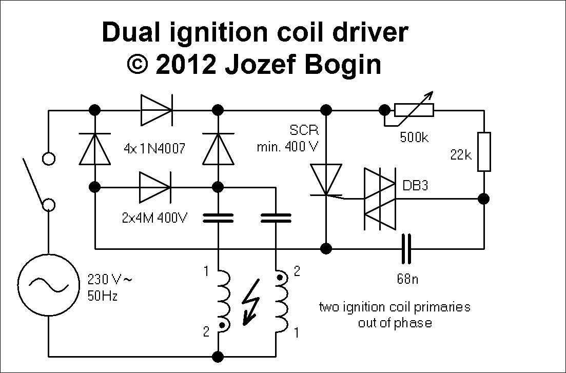 Schematic, click to enlarge
Simple, isn’t it? Mains with light dimmer in series, potentiometer regulates SCR’s conduction angle; two run capacitors (for current limiting) and two ignition coils in out of phase. I’d recommend lower capacities if you do have those modern coils, though. And because it runs straight off mains frequency, the sparks have a loud distinct growl – totally incomparable to my flyback drivers. 🙂 It overloads my camera’s microphone, too.
Because a two-coil setup, such as this one, greatly exceeds the output voltage ranges your ignition coils were designed to operate in, you might be plagued with arc-overs to the primary. Don’t let it burn a conductive trace once – the sparks alone aren’t as powerful as flyback arcs, nevertheless use any good insulating material such as glass, silicone, hot glue or rubber to see if it helps.
Hello, I have 13 jears end I began experimenting with high voltage with 12. I build dis circuit end modified it to one singe ignition coil, it works perfectly, I love you new website.
Ps. I built you tesla coil with 12 end it worked!!!!
I’d just look at the pinout at its base and determine anode, cathode and gate from the datasheet.
jozef, it’s an scr but for some reason the diagram that came with it shows a + on the same side as the gate, and – on the other side. essentially saying that it should be connected the opposite way round to every other thyristor diagram i’ve seen
What kind of thyristor is that ?
Hi jozef, I bought all my parts however my.thyristor spec shows it the opposite way round to.yours? It says the ground should be connected to the terminal that your schematic has the bridge connected to, and the side you have connected to your diac mine says should be the positive side
Would you be able to shed any light on this? Are they supposed to be like that or should I have my thyristor wired differently to your diagram?
apologies, i misread!
what calculation did you use to decide on this capacitor?
It’s a phase shifter. The value is nothing crucial, anything between 68 to 220n can be used.
It’s 68n, not 68p. I’ve never seen an electrolytic cap this small.
I’m struggling to find a 68pF capacitor of the correct rating, would it be possible to use a slightly different capacitance here? and does it need to be an AC cap or will DC work?
The diac /DB3/ has a breakdown voltage of approx. 40 volts.. about the thyristor I can’t remember really. I think it was BT-something in the 600V range.
also final question i think,
what current rating did you use for the SCR with regard to gate trigger current and holding current?
thankyou, what breakover current rating did you use for your diac?
I did use an SCR as a half wave chopper, because full-wave through a TRIAC (which is used in most dimmers) will bring you just more heat stress on the coils and is not really needed – it didn’t bring more power in; not for me at least.
thankyou!
did you use an off the shelf dimmer or did you put the components together for it yourself?
The capacitors will impact the current on the output mostly. The higher the capacitance, the lower their reactance (“resistance” to the 50/60Hz AC current passing through) will be. This will result in a greater power output and “hotter arcs”, but you need to take care for the coils so they do not overheat.
The output voltage depends on the waveform created by the SCR and its conduction angle. Generally, if your coils are rated 50kV each, you should be fine.
whoa whoa steady on there, I was only asking some advice because i didn’t grasp the disclaimer properly!
in actual fact my job involves working on high voltage switchgear handling several hundred amps, so please do not mistake me from a hell bent on distruction numpty with no electrical knowhow.
all i said is that i wasn’t used to the system of notation you used, I didnt mean to offend.
I only ask because I think this circuit is brilliant, I’m hoping to use it with a pair of HEI coils i have, however I’m a little stuck on how to size my capacitors accordingly. would you be able to shed any light here? the coils are rated at just shy of 50kV
No, you did not read the Disclaimer as you were instructed to do so on the main page, otherwise you would not have asked such a question – where, along with the obligatory safety warnings, the notation I use (which, in fact, is a standard defined in the ČSN/STN norms) is clearly and understandably explained. In this case, it is indeed 4 microfarads.
Per your question.. Have you EVER seen any run capacitors outside the microfarad range? Do you have any idea of their role in this circuit? A 4 nano- or a 4 picofarad capacitor would exhibit a capacitive reactance so high that the current passing through the ignition coils would be hundreds of microamps, hardly of any use here !
And I don’t give a shit about what you are used to. If you don’t like my circuit, then don’t build it. Lacking the proper know-how and also being ignorant of the facts while constructing high voltage circuits makes you a perfect Darwin Award nominee.
I did however i just wanted some clarification, am i right in saying 4 micro farads??
I just dislike the notation used as it’s different to what I’m used to!! would you be able to clarify all of the values in the schematic in standard engineering notation? (micro, nano, pico etc) I’d be very grateful, I don’t want to end up frying components if i can avoid it!
You did read the Disclaimer didn’t you? 🙂
Hi, I have a line voltage of 127 volts, what modifications will be necessary to the circuit? Thanks in advance!
You can use a 250k pot and higher capacity, lower voltage-rated caps. You’ll get lower voltage on output but you won’t stress the coils that much.