With a predictable demise of CRT screens that’ve been phased out of production since the late 2000s, the owners of vintage TVs, monitors or other displaying equipment, kept in a condition that’s just too good to be thrown out, will eventually bump into a problem concerning each and every CRT – or any vacuum tube in general – of decreased cathode emission, reducing its overall brightness. Fortunately, there might be a way to mitigate this, extending the usable life of the CRT by a few months, or even years. This is where a simple regenerator circuit steps in.
 Improvised regenerator circuit
The circuit described here was originally published in a December 1978 edition of a Czechoslovak magazine “Amatérské radio” (Ham Radio) from an unknown author. Since then, it was in use for decades by repairmen and hobbyists alike. I have redrawn the circuit and made some improvements to it, to make it more versatile and reduce the possibility of damaging the CRT screen while performing the regeneration.
On a CRT screen that still has good vacuum and healthy phosphor coating, the most common cause of brightness decrease is a depletion of the barium oxide layer of the cathode, which results in reduced emission of electrons from the electron gun. In such a case, this depleted oxide layer can be blasted off the cathode, by means of high voltage, peeling it off and exposing the remaining non-depleted oxide layer. This is the basic principle of this regenerator circuit, and when successful, it can restore operation of the screen at nearly full brightness for some time.
Please note that this circuit works best with vintage CRT screens only (with a sufficiently thick oxide layer, where money haven’t been saved on). Preferably monochrome ones. It certainly won’t work with Trinitron screens, CRTs with depleted cathodes caused by a hack to permanently increase the filament voltage, or screens with a degraded phosphor – due to burn-in, or long term exposure to light, or similar.
Although there have been successful reports with “modern” color CRT screens; if you can – at first, try fiddling with the SCREEN potentiometer directly on the diode-split flyback, it might be as simple as that. Only when you start to observe horizontal retrace lines on the screen, you know that the CRT has gone weak enough for this experiment to have an effect.
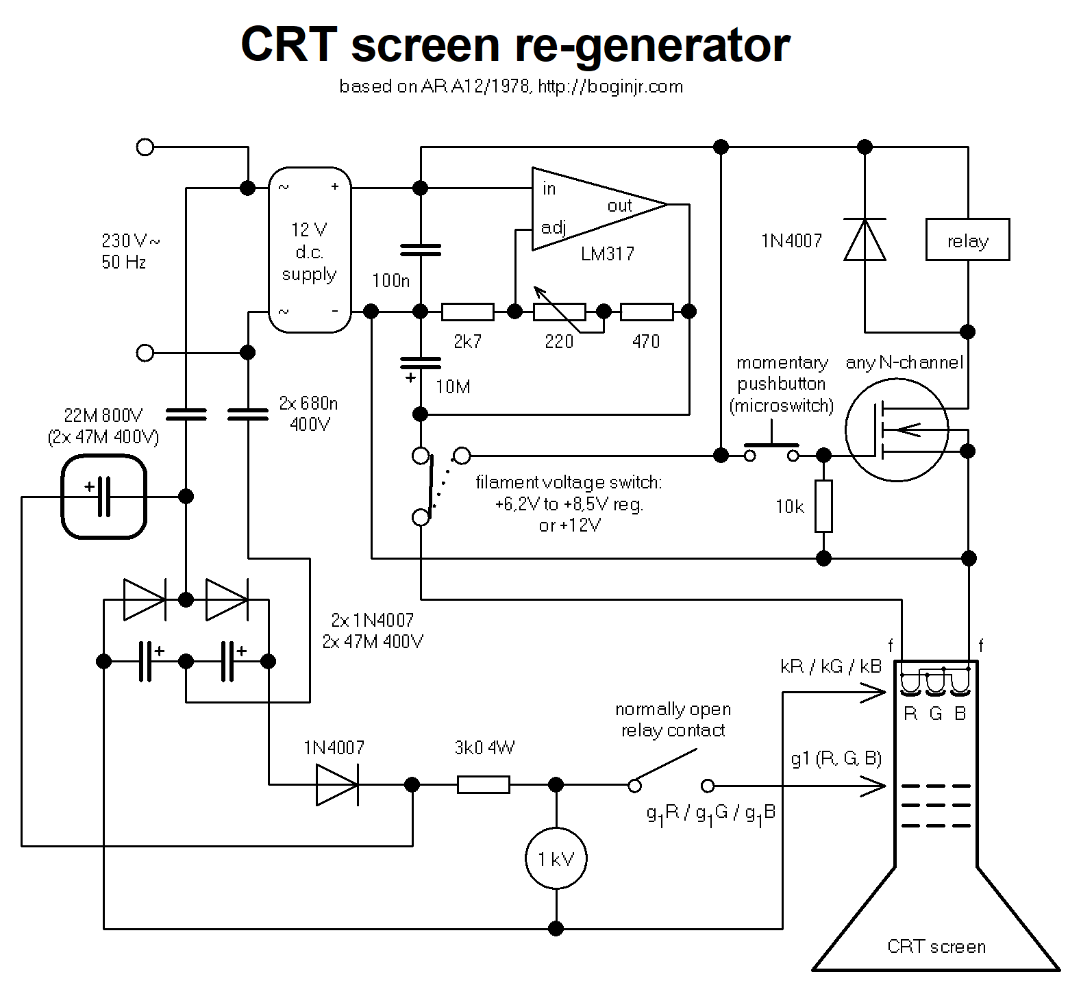 Schematic (click to enlarge)
In this schematic, the CRT screen is connected like a vacuum diode – with the first grid (Wehnelt cylinder) acting as the anode. In case of connecting a color screen, you need to connect the particular cathode connection (red, green or blue) with a matching g1, and do the regeneration process for all three of them. You can also short all three cathodes together with the cathode input of the regenerator, and just connect the appropriate g1, to make the wiring simpler.
The circuit works as follows: There’s a regulated filament supply for the heater, consisting of a twelve volt d.c. supply that can provide at least 400 mA with some headroom, and an LM317 linear regulator (with a small heatsink) that brings it down, as most CRTs have a heater voltage of 6,3 volts. However, you might need to use a slightly elevated voltage during the process (see below). There’s a switch to bypass the regulator, providing a 12 volt heater supply for certain CRT screens with a filament voltage of 11 to 12 volts (like the one I’ve used below). The original 1978 schematic required the use of a mains transformer with appropriate taps, and a single pole, multi-throw switch, disallowing smooth filament voltage regulation.
High voltage supply for the first grid, which is required to disintegrate the depleted oxide off the cathode, is obtained straight from mains through a voltage tripler, consisting of a Delon bridge (a full-wave voltage doubler) with a super-imposed sinewave on the output, giving approximately +950 volts on output with no load.
The two 470n bipolar capacitors are used to limit the charging current of the capacitors used in the multiplier due to their AC reactance, and also they make the circuit DC floating, so the thing won’t draw short circuit current, should e.g. mains ground be inadvertently introduced to the regenerator. A 3k resistor of sufficient wattage is used to save the CRT internal connections (and also the relay contacts) from welding shut, in case of overcurrent or a hard short.
There NEEDS to be a momentary switch without latching, operating the high voltage output, because you will need to turn the g1 supply instantly OFF in case of overcurrent. I have made an improvement so you can use any small microswitch to do this. However, if you have a beefy push button (e.g. from a soldering gun, or similar) that will withstand the high voltage, you can ditch the transistor driving the relay coil and use it directly in series with the g1 supply. Also, with a relay in place, if your circuit is enclosed properly, the g1 supply won’t shock you when you disconnect the circuit from the mains, as the relay will only actuate with twelve volts on its coil, whether you push in the button or not. Of course, before fiddling with the circuit, be sure to discharge the capacitors.
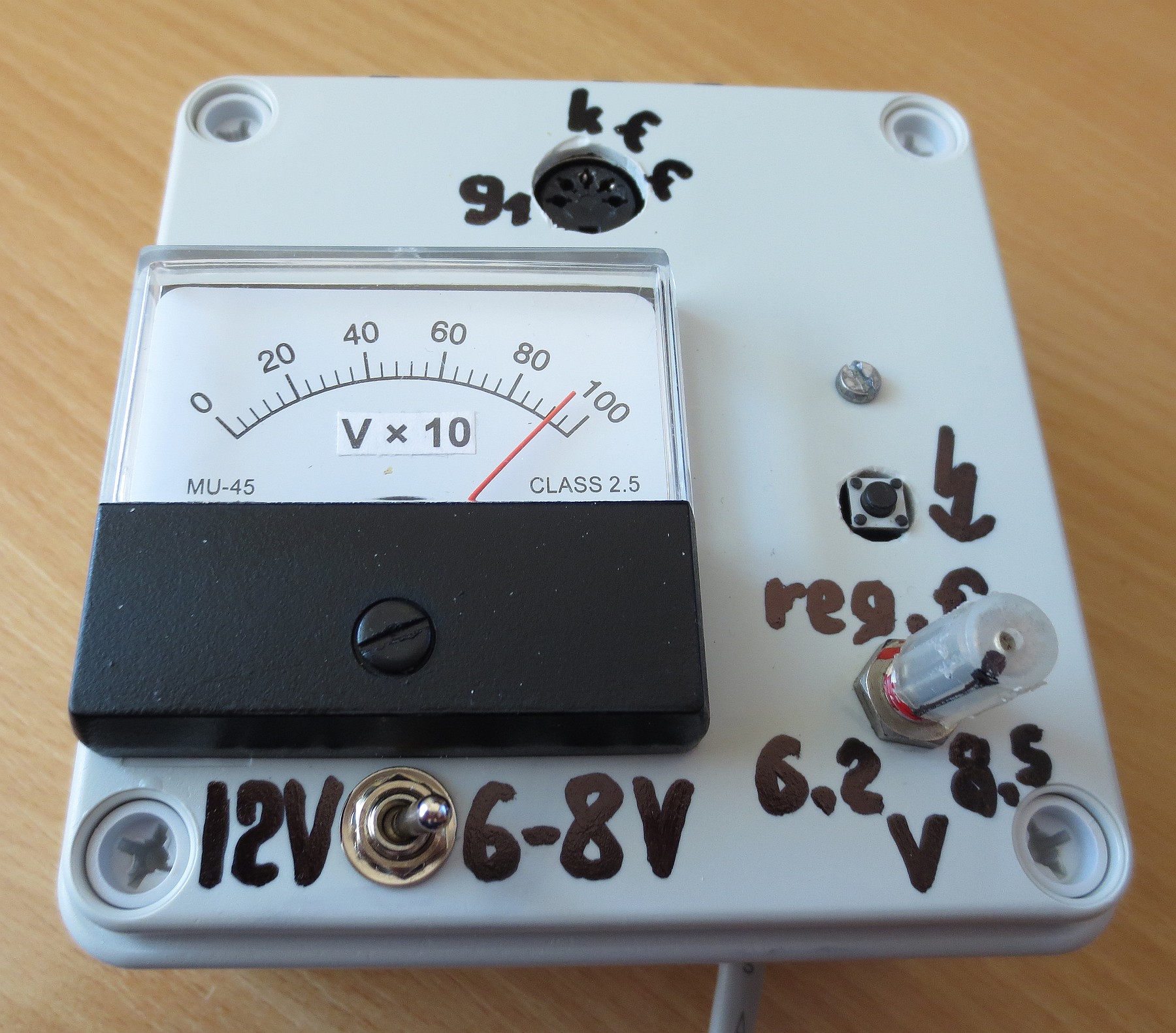
The original design also used a small neon glow lamp with a voltage divider to indicate high voltage (or its drop) on output. It’s a much better idea to use a voltmeter though. Any d.c. meter, analog or digital, up to 1000 V, with an internal resistance of at least 10 megohms, will work.
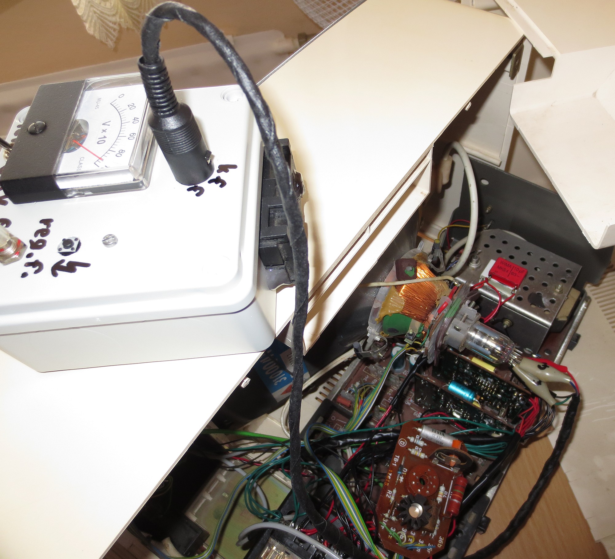 Regenerator in operation.
The circuit has been successfully used to restore full brightness of a “3100041” green screen CRT in a Tesla PMD-60.1.
Verify the circuit works as it should before proceeding with regeneration!
The filament voltage should be freely regulated between circa 6,2 to 8,5 volts, or direct 12 volts, depending on the switch. You should hear the relay actuate on button press and it should immediately disengage when you let go. If the circuit is plugged in to mains and idle, the meter should show 940 to 950 volts.
The regeneration process is as follows; in order not to destroy the CRT, be sure to read it thoroughly:
- Be sure the TV or monitor is turned off and unplugged. Then, open it up and detach the whole PCB with the socket, which is connected to the base of the CRT screen. You will need to connect the regenerator to the pins of the screen directly. Do not touch the anode of the CRT and do not disconnect the high voltage suction cup. You don’t need to discharge the CRT in this process.
- Turn down the filament potentiometer to 6,2 volts, then flick the filament voltage switch either to the regulated position, or to the fixed 12V position, depending on the cathode heater. Consult the datasheet of the CRT for more information on what your screen requires. Also, take careful note of the pinout.
- Connect the filament heater, cathode and g1 wires to the base of your CRT, according to its pinout.
If using a color screen, use the grid for your respective cathode, red, green or blue and repeat the process for all three.
You should observe the filament heat up now. - After at least 2 minutes of the cathode heating up, start observing the voltmeter, take a note of the current reading and finally press the button. The voltage on the meter should drop down by at least 150 volts, indicating cathode current flow. If this is the case, continue holding the button and proceed with the next step.
If this does not happen, let go of the button and try pressing it repeatedly, in a fast manner.
If it still does not result in a voltage drop, disengage the button, slightly increase filament voltage (in 0.25 to 0.5 volt increments), wait at least 30 seconds and repeat this step.
Should you hit 8.5 volts without any observable cathode current, the CRT most likely won’t be helped. As a last resort, you can flick the switch to 12 volts filament, but this will greatly increase the risk of damaging the CRT. So if it still works somehow, stop here. - Continue holding the high voltage on button for approx. 15 to 30 seconds, observing the voltmeter. After that, let go of it. If using a color CRT, do the same process for the rest of the cathodes and grids. Then reassemble the PCB with the socket back and test the TV or monitor. Repeat the whole regeneration process if necessary.
- WARNING! If, during the process of regeneration (or immediately upon the relay coil actuating) you observe a short circuit, ramming the needle of the meter near the zero; or a voltage drop of more than 500 volts which is increasing fast, let go of the button immediately!
Then disconnect one wire of the heater supply for at least 2 minutes to cool the cathode down. Then, decrease the filament voltage by half a volt, connect the heater back, wait at least 2 minutes and try again.
If overcurrent happens even at the lowest filament voltage setting, disconnect the heater, let it cool down for a few minutes and then actuate the high voltage without the heater. If this does nothing, keep the button held and reconnect the heater. If it still results in a short circuit even without the heater on, the CRT is shot – there might be a hard short circuit between the cathode and the heater, or the grid.
But should there indeed be a hard short somewhere where it shouldn’t be, you might try – what the heck, the screen is considered K.O. anyway – lightly tapping on the electron gun with a rubber piece (be careful you don’t break the neck, ruining the CRT for good). Or try a 220 microfarad capacitor charged to at least 400 volts to obliterate it. Wear ear protection if you like to keep your head up close to various things 🙂
And that’s all, folks!
The circuit was used to restore full brightness of the Tesla PMD-60 monochrome monitor, whose screen was visible only with the brightness pot turned all the way up, and it’s still ticking like a clock. Should the screen in a Merkur get worn out one day, it will meet the might of this circuit 🙂