
Description: A portable full-track tape recorder.
Manufacturer: Kudelski SA
Made in year(s): 1958-1968
Country of origin: Switzerland
Status: Working
A finishing touch to my small collection of quarter-track and half-track reel-to-reel tape recorders, is a Swiss made full-track portable tape recorder, produced between 1958 and 1961 in Prilly, canton of Lausanne, and from 1962 right until 1968 in Paudex, canton of Vaud, Switzerland. Being battery powered, these machines were heavily used by TV, film crew and radio reporters to record news events from all over the world, even behind the Iron Curtain, right until the mid-nineteen eighties.
During playback, with the dust cover down
This particular piece that I’ve managed to get my hands on, was made in 1967 in Paudex, and was used by at least 2 different entities, including Radio France and a studio in Belgium.
The serial numbers of these machines began either with an NP or a B, preceding the number. The NP variants were to be used with film, as they shipped together with a synchronization signal circuit (the Pilottone, later NeoPilot, marketed by Kudelski) and a separate NeoPilot combined record/playback head, so that the tape recorder could be connected to a motion picture camera, recording sound in sync with the film. The B variants omitted the NeoPilot head and the sync circuit; these recorders were marketed to be used by radio reporters.
An H suffix was added to both B or NP variants that optionally shipped with a small 2 watt audio amplifier, connected to the internal speaker.
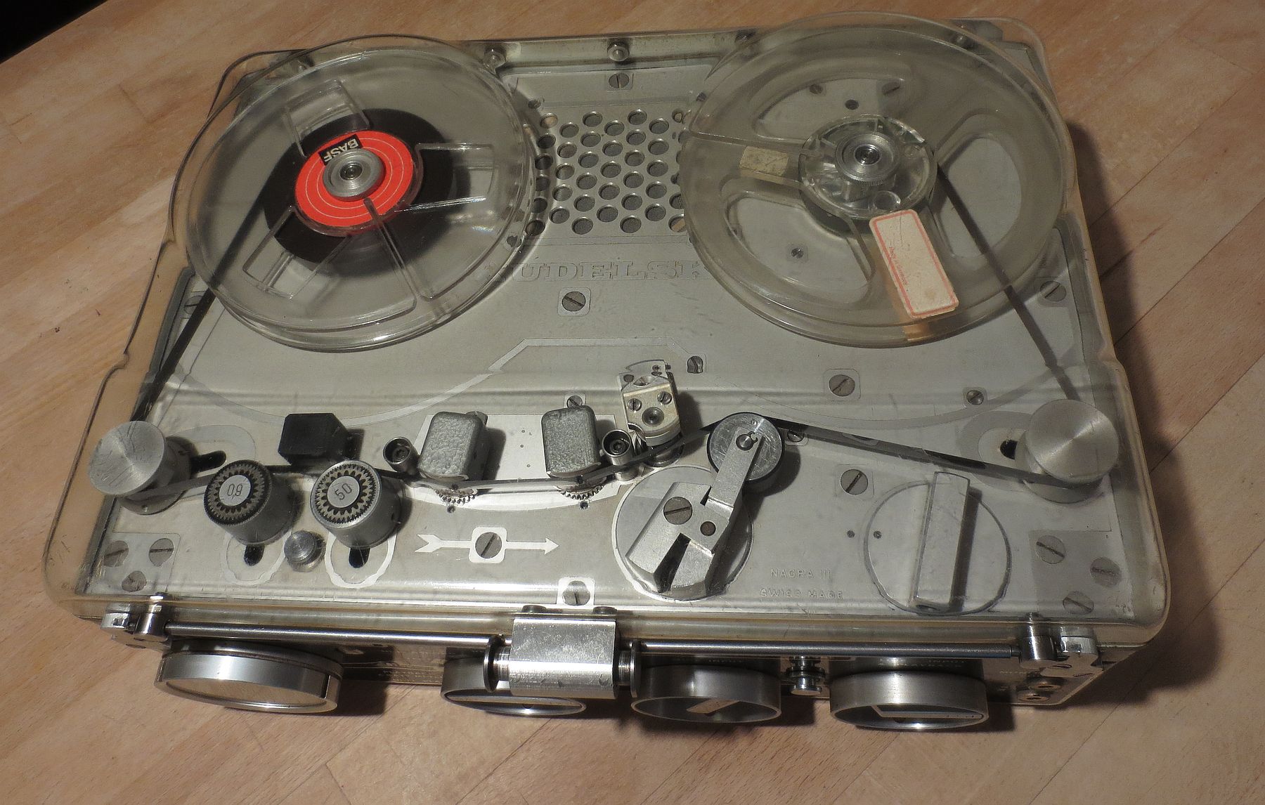 Top view with the dust cover on, with tape transport set to the idle position
This was also the first Nagra to employ transistors, printed circuit boards, a DC motor for the tape transport, with electronic speed control and stabilization; as the predecessor models (Nagra I and II) were vacuum tube based, and had a mechanically governed clockwork motor that had to be wound up with a crank, like an old phonograph. The machine and its rugged, but precisely engineered internals, are a delight to look at – despite the design being over 60 years old, and also showing heavy signs of usage, the machine required no major service to start spinning and playing tapes (we’ll get to that later on).
Despite all of that, the machine almost screams professionalism, and its controls get the message through, that it had not been targeted to be used by a layman. Heck, even the reporters had to be at least somewhat professional with what they did for a living… Compare that to what you see today on the TV 🙂
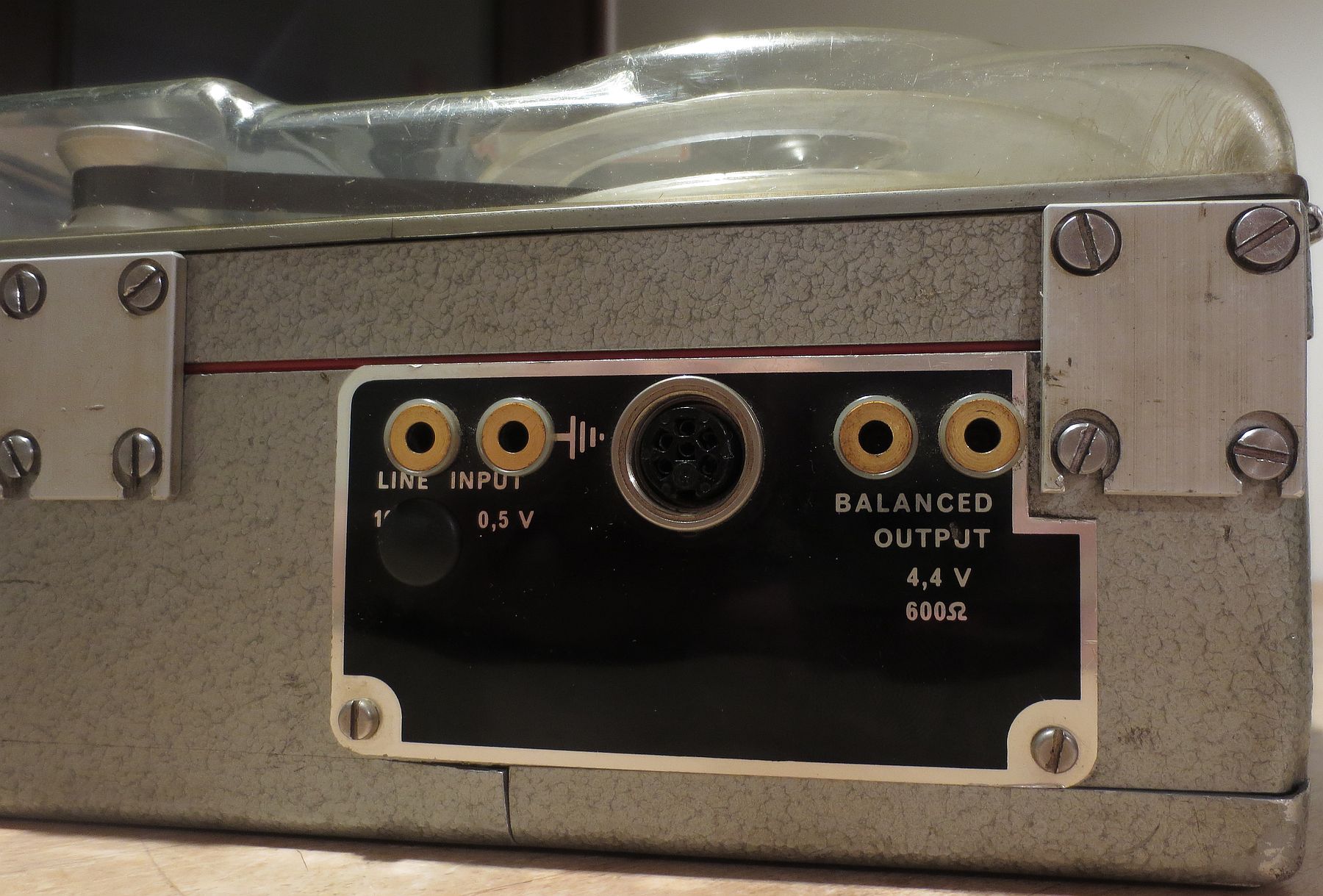
 Front panel
Okay, so what is this machine hiding in its vitro? We have a tape recorder designed in the late 1950s, so the transistors were the hype. To be exact, germanium PNP transistors exclusively, and over thirty of them are inside. Three tape speeds are at our disposal, 9.5, 19 and 38 centimeters per second (3 3/4, 7 1/2 and 15 inches per second, respectively), with the 19 cm/s speed switchable between 2 types of recording equalizations, either following the DIN/CCIR or the American NAB (Ampex) standards. For recording and playback, a balanced XLR microphone input and a 600ohm (0dB == 4.4V) balanced output are provided; in addition to a low-impedance monitoring headphones output and a classic line input, both unbalanced. There’s also a 6-pin DIN connector to connect other Nagra peripherals, an external power supply, a remote control for the start-stop, and more.
Since it is a full track tape recorder, it uses the whole width of the tape to record a single (mono) signal in one direction only. The machine can also be used to play back half-track recordings, if the tape was recorded in stereo (that is, both tracks in the same direction). Or, alternatively, to listen to a 4-track studio recording, with all tracks in the same direction (i.e. not recorded by a consumer-grade stereo quarter-track deck, otherwise you get the other 2 tracks mixed in reverse). Of course, all of that only in one mono signal.
The maximum supported reel size is 18 cm, or 7 inches in diameter, but the dust cover can only be closed and utilized with a maximum of 13 cm (5 inch) reels.
 An XLR connector to a mic for a 1950s device? You bet…
Of course, being a full-track recorder, it accepts single channel mono sound, and in one direction of the tape only.
The machine employs a (brushed) DC motor to move the tape transport, which itself is very rugged and can be used in any position of the machine, even upside-down. It keeps stable speed “on the go” even when carried, moved or shaken (to a certain extent), without ugly flutter. Any speed variations can be observed with a 50 or a 60Hz light source, shining on the 2 flutter reducers/tape tensioners next to the erase head, that have strobe markings on top of them. These can also be used to check and calibrate proper speed.
The tape transport is controlled by the user by means of a big rotary switch that actuates the linkage. This switch has a black indicator circle and needs to be carefully rotated into its three main positions: the playback position, which has a detent, where the indicator circle points straight up, with the pinch roller engaged; then the storage position (without a detent) that disengages the linkage, when the indicator points to the black circle on panel – this is the stowing position for the machine, to avoid unnecessary wear and tear of the clutches; and last but not least, the rewind position, which engages the linkage to move the tape backwards, and clicks a small switch to override the speed stabilization circuit, allowing the DC motor to run on full supply voltage speed.
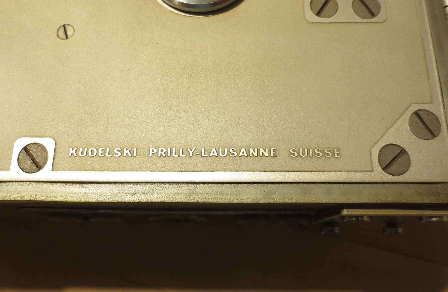 Proudly Swiss… Although it does say Lausanne here on the top panel on all machines, this particular piece was assembled in Vaud.
One interesting thing to note is that the machine does not have a dedicated tape counter, nor a fast-forward function. I think the machine was presumed to be operated in one direction only, so that the reporters have no reason at all to fast forward their tape on a machine like this: with what they’ve obtained during their reports and recordings, they’d return back to the radio or TV studio for further processing on a studio machine, where it would have been edited accordingly. In other words, leaving this machine to be used “in the field”, inside some big leather carrying bag, with the tape transport engaged into playback the whole day, mainly using the record functionality and only rotating the power switch, with a microphone in the other hand. That at least is my theory…
However, there is a momentary push-button (with no marking on it) under the erase head/strobe indicators that override the electronic speed control, allowing the motor to run full speed from the supplied batteries, or external power supply. Since the electronic speed control kicks in after the button is released, the tape still goes over the heads and the pinch roller is pressing against the tape. So it does run faster, but it isn’t a dedicated fast forward function per se, as the tape is still engaged in the transport (plus, the button is also used for certain cases, shall the DC motor not start properly). Kind of like fast-forwarding with cueing. But the rewind is much faster, as the tape transport is disengaged in that case…
 4mm banana jacks for “everything”, and a threaded 6-pin DIN connector for the rest
Since the front-panel power switch switches the motor on in every occasion, except when in “STOP” or in the “TEST” mode (which is used, in conjunction with the VU meter, to set the input volume right before recording), you need to switch the tape transport accordingly, before turning the machine on with the main panel mode switch. It all kind of reminds me of the IT-65 Geiger counter which is also from the nineteen sixties: a black panel, a rotary switch with a needle meter next to it, the first option being “TEST”, and all… 🙂
Also it is a little bit tricky to have the motor on and the tape transport stationary, like in a “pause”. For this to work, you need to rotate the tape transport switch to a “biting point” in-between the storage and playback positions, so that the black circular marker “kind of” points at the screw that is right next to it. But – if there is no tape in the transport, the take-up reel will spin freely no matter what, though. This is by design.
During the recording mode however, the machine will not fast-rewind – this is a safety feature, as the erase head is still HF-energized by the front-panel power switch. Since it is still touching the tape, it would have erased everything what has been rewound if it wasn’t for this safety feature. (Spin the reels manually with your finger to see for yourself.)
With the tape motor on, one also needs to be very careful while rotating the tape transport switch: about halfway through from the Rewind mode, without a felt “detent”, the transport linkage switches direction of rotation from backwards to forwards, but does not fully engage the pinch roller yet. It’s a best bet to give the mechanism time to slow down from the rewind mode, or only use the front panel mode selector to actuate the motor on and off, in order not to stretch or rip the tape from carelessness.
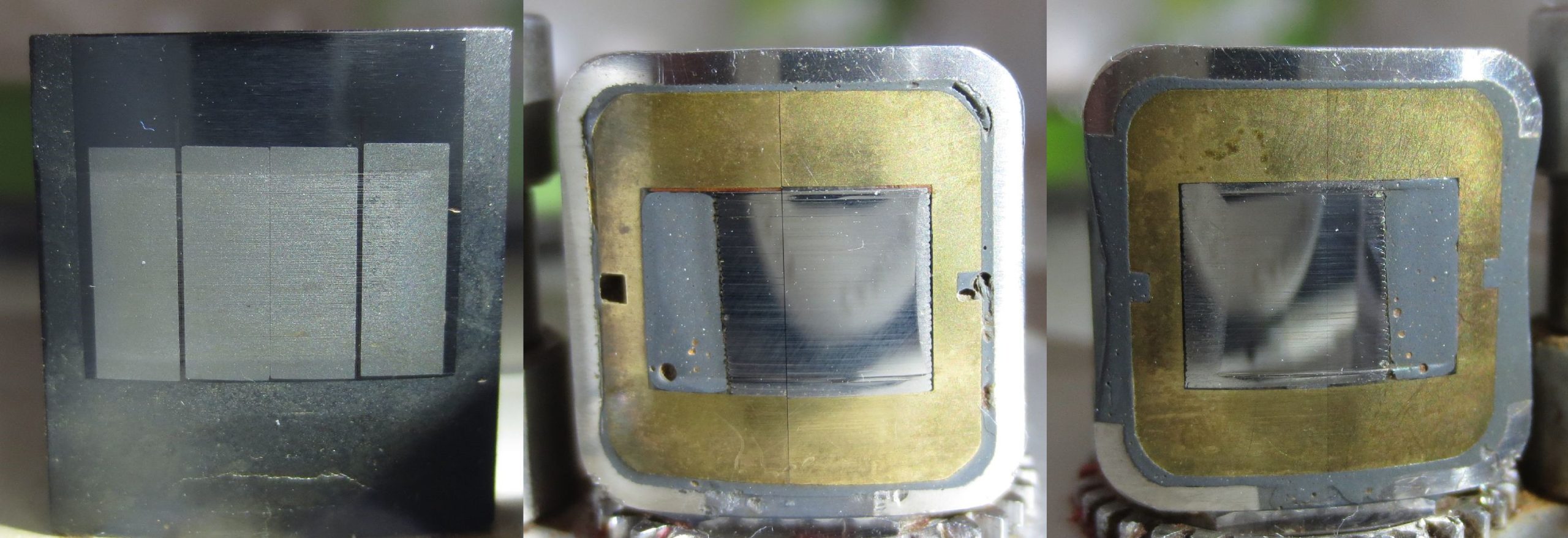 From left to right: the erase, record and playback heads.
(I do not have the NeoPilot variant, unfortunately.)
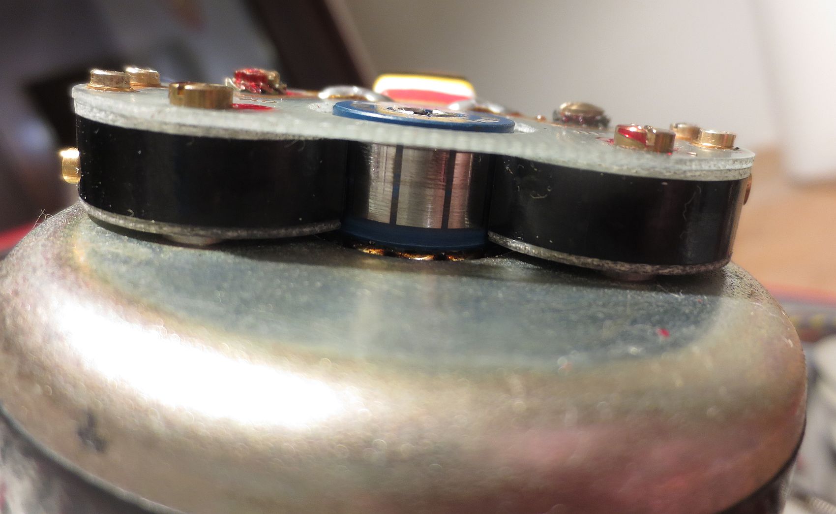
As far as the speed stabilization goes, the one and only DC motor in this machine is spinning, on the same shaft as the capstan, a ferromagnetic “cogwheel” with fine ribs in it. In an enclosure, in a very close proximity to this disk, is a magnetic pickup, which is sensitive to these serrations, when the disk is rotating. As the “ribs” are magnetic, this induces voltage in the pickup (of about 3 millivolts), this is then amplified and fed into the motor servo circuit, governing the proper speed instantly when the machine is turned on: the 9.5 cm/s speed is achieved through PWM by maintaining a 1 kHz signal from the pickup; 2 kHz for the 19 cm/s and 4 kHz at 38 cm/s tape speed. The manual calls this pickup a “tachometric head” and the serrated disk as “tachometric wheel”. Certain modifications done to the Nagra also accept a custom speed signal; these recorders have a small coaxial input next to the speed selector, so that they can lock onto different speeds (e.g. 4,76 cm/s or faster than 38 cm/s).
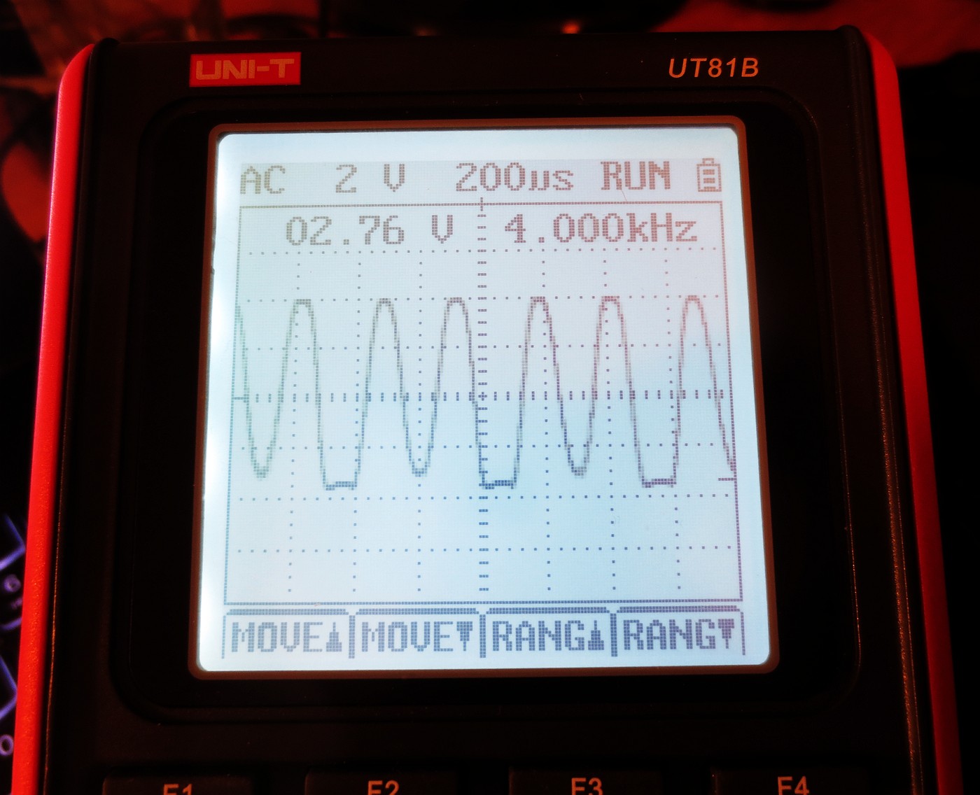 Amplified “tachometric head” output at 38 cm/s on the UT 81 scopemeter
At the time of writing this article, there weren’t many good service manuals available on the internet for this tape recorder. We do have a user’s manual, and there are a couple of extended “operation manuals” that describe the known caveats of the construction, the electronic speed control, usage of batteries etc., dated 1963 and 1967. We also have a translated version of these manuals from Czechoslovakia, which has been incorrectly referred to as being in Polish, but that’s about it. We do not have an official service manual publicly available, which is not the case with the newer Nagras or Revoxes.
As an example, to get the front panel out (so I could straighten a couple of dents and nicks in it), you need to gain access to the nuts that hold it in place, which means dismantling almost the whole machine, to take each of the modules safely out. While doing that, you also need to get the modulometer out, which requires the use of an appropriate C-spanner.
Also, the English manuals have a hint of French in them, perhaps relative to the place (the French-speaking portion of Switzerland) where these machines have been manufactured in. As an example of this Frenglish that can be observed in these manuals: the VU meter with a custom fancy Nagra timebase is called a modulomètre (with the reader being introduced to its construction as being similar to the d’Arsonval galvanometer – yes, very helpful, why just not call it an improved microammeter instead); the magnetic speed pickup is a tachymètre, the DIN connector is a Tuchel connector, rechargeable battery is described as a Leclanché cell or as an accumulator, and the tension stabilizer has nothing to do with the tape tension at all – with this terminology, the manual is referring to the -10.5 volt internal regulator circuit. Hon hon hon hon, monsieur. 🙂
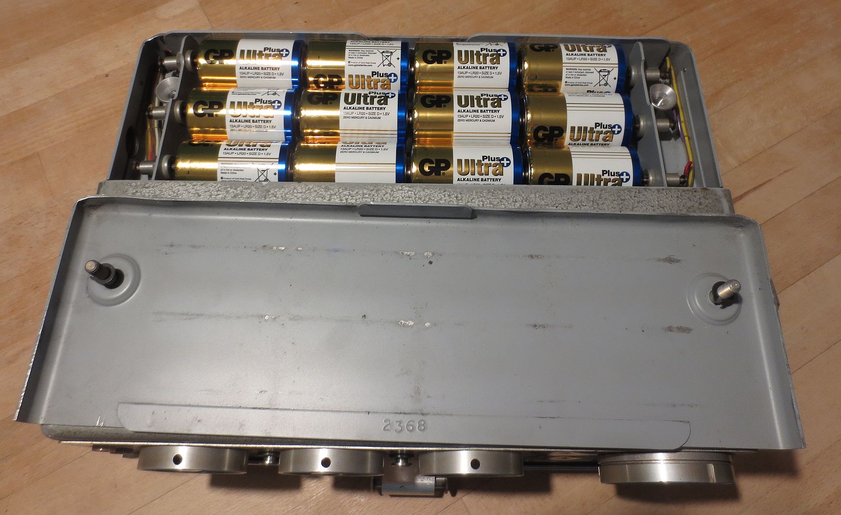 Runs from 12 D-cells, or from an external supply
The machine was designed to run from twelve D-size batteries, which increase the overall weight of the machine by more than a kilogram, but you can hack in a 14,4 volt NiMH battery pack into the battery compartment, or you can use AA to D cell plastic adaptors and use any modern NiMH cells in the machine without any issues, you could even recharge the battery pack through the DIN connector, if needed.
By all means, the supply voltage can be anywhere between 12 to approx. 24 volts, as there’s an internal 10.5 volt stabiliser for the rest of the circuits. The only thing that runs on full operating voltage, is the DC motor in the rewind or momentary fast-forward modes. So the higher the supply voltage, the more the winding speed you get. Do not go over 24 volts, as the electrolytics might release some magic smoke, and proper polarity needs to be observed too!
If the speed stabilization cannot reach the proper maintaining speed, due to exhausted batteries or whatnot, or if the machine is in the rewind mode, – a high-pitched whine is injected into the monitoring headphones (but not into the balanced output). The VU meter also acts as a battery indicator during “non Hi-Fi playback”. Nevertheless, the manuals specifically hint to avoid using the VU meter battery reading, especially in the 38 cm/s mode, and to listen to the monitoring output instead, if there’s the whine during playback, or not.
On the other hand, to get rid of that low-battery-warning whine in the unbalanced monitoring output, use the Line Input ground jack instead of the Monitoring Output ground, where this signal is being injected into.
But the manuals also warn you from impending doom if you dare to try dismantling the rotor out of the DC motor, unless you insert a magnetic shunt bar – or else the thing will degauss, divide by zero and you would need to ship the motor back to Switzerland to get it remagnetised. (Putain! Good luck with that then.)
 The peripherals that can be connected to the recorder, including a power brick
The 6 pin DIN, or “Tuchel”, connector can also serve as an external power supply input. However, if the machine is not planned to be used from the batteries, care must be taken here: due to the thing being designed in the late 1950s, it uses PNP bipolar transistors exclusively, and as you all might know, these transistors operate on a negative voltage supply, i.e. with respect to the emitter.
Thus, like any other PNP-transistorized device of that time, the machine was constructed with positive on ground. With batteries inside, or a 2-prong mains power brick that has no connection to the mains ground, that means, it is floating, you do not have to worry about this: you connect the positive pole to the input prong marked “ground”, and the negative pole to the supply voltage input.
With a power supply that is connected with mains ground, i.e. with a 3-prong cable, like certain laptop chargers or 12 volts from a PC power supply or whatever, you cannot use this approach. The tape recorder would still happily run with e.g. +12V on the tape recorder ground prong, and with mains ground on the supply voltage prong of the tape recorder, but a nasty surprise will wait for you when you attempt to connect an another device that has negative on mains ground – like a computer soundcard connected to the Line Input of the tape recorder. This will instantly short out your non-floating power supply through your audio device straight to the ground.
So, with power supplies that indeed are connected with mains ground, you need to make sure they are providing a negative voltage rail with respect to ground (with a current rating of at least an amp) for you. In that case, you would connect mains ground to the ground of the tape recorder, and the negative voltage rail to the supply voltage prong of the DIN connector.
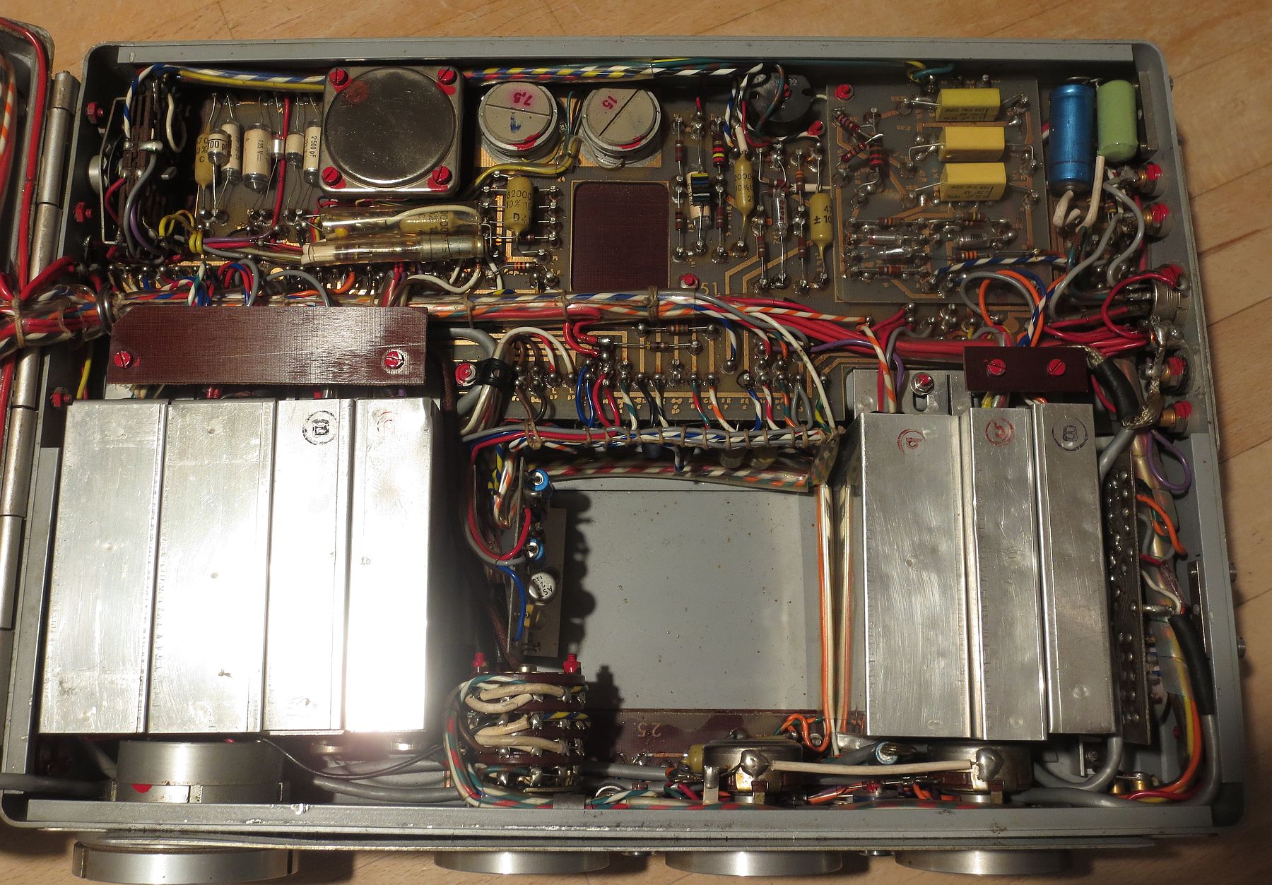 Now this I call a work of art… if you don’t have to touch it
The machine uses printed circuit boards, but their design largely predates any modular system with bus connectors on the PCB, for fast replacements module-by-module…. precise hand work went into this. This of course has the advantage of being rock solid, but you need to be very careful while following each wire lead, and you need to take good care what did you disconnect, and from where.
The problem here is that these machines were updated more than once during their production, and you cannot rely one-hundred-percent on the schematics you find on the internet. A nice example of this can be the tension stabiliser, pardon, the -10.5 volt regulator (the third module, in the aluminum sheath from the left): there shall be a trimpot to fine-tune the output voltage… hmm, nope, not in my revision. Or the addition of an internally switchable impedance between 50 or 200 ohm for the mike preamplifier, by rewiring the input transformer. Or the Monitoring switch.. before tape and after tape 🙂
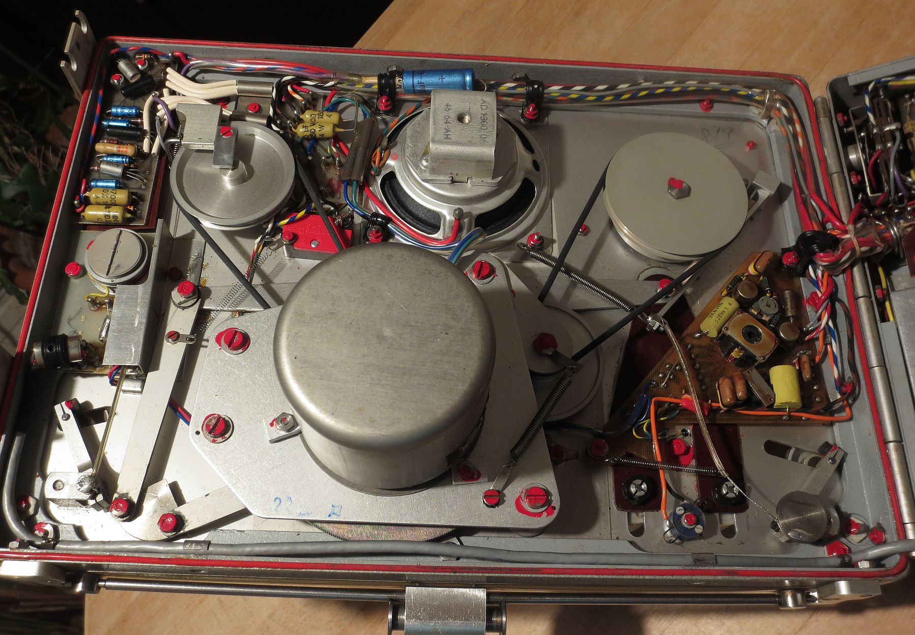 The motor, HF bias oscillator, 2 watt push-pull amp for the speaker, and the tape transport linkages
And there are lots of different “quirks” that differ between revisions: around 1962, an unmarked push-button to inject the “tachometric head” oscillator output (1, 2 or 4kHz signal) to the line input, was added to the Nagra, perhaps to test itself (to set 0dB, or to test its own wow and flutter?) during recording. And in 1963, another new push-button appeared to the left of the microphone volume potentiometer, this time, it was marked as “BA”, or “before-after”, to switch the monitoring to either tape, or source. Because defaultly, the Monitoring Output in a Nagra III during recording, is connected to the playback head, i.e. whatever has been recorded successfully. And when this button is pressed, you get what is fed to the record head, i.e. the input source (microphone, or line in). But wait! In both cases during the recording, the VU “modulometer” still shows the audio level ON the mic or line input, and NOT the modulation from the tape (from the playback head)! So to see if the recording levels are fine, you need to stop and rewind the tape, put the machine into Hi-Fi playback mode and regulate the Line Input & Playback potentiometer to exactly 0 dB – so that the playback is neither attenuated or overamplified – and use monitoring headphones and no load on the balanced output (in order not to put a load on the output).
As such, also in the Hi-Fi playback mode, if the Playback potentiometer is not set to 0 dB exactly, the VU modulometer does not show the actual modulation of the tape signal, but the VU of the audio output of the machine, i.e. 0 dB on the modulometer corresponding to 4.4 volts on the balanced output.
And in the regular, “non Hi-Fi” playback mode through the internal speaker, it does not show any VU at all. The needle acts as a battery indicator reading. Sigh. 🙂
 When was the last time you’ve seen handwriting and engineer’s comments etched on PCBs in a commercial product?
There were a couple of issues with this tape recorder when I’ve obtained it first. To mitigate the noisy commutation of the brushed DC motor, it was enough to gain access to the commutator and brushes, clean them with some acetone and then apply a very thin layer of grease to shut it up, yet still maintain proper electrical contact of the brushes to keep the motor spinning away reliably on all speeds, and on fast forward. Additionally, the whole commutator is kept enclosed, so that no foreign dust that would hinder the commutation can be introduced, at least without voluntarily doing so. 🙂 And thankfully also, there’s still some life left in the carbon brushes, not being worn down to the nub…
 The commutator. The brush holders are on the sides.
The rotor is directly underneath in the enclosure.
The owners before me also re-wired the 6-pin DIN connector to their own liking, which was a surprise I haven’t welcomed, but I have managed to restore the original pinout in the end. One of the connections they also got rid of, was the “start/stop” wire from the servo motor circuit… unfortunately, they also removed an RC network that prevented the speed stabiliser from overshooting through the starting speed, directly upon power up. This was mostly evident on the 9.5cm/s speed, when the “tachometric head” outputs the smallest voltage… the motor spun to the maximum speed for a while, before stabilizing itself.
The technical manual on this stated, that the “starter discharger” was not working properly because of one of the germanium transistors or one of the diodes were failing… luckily for me, they were wrong on this one. 🙂
There was also one dead short, caused by a malfunctioning foil capacitor, in series with the recording head on the 19 cm/s NAB equalization setting. This caused an enormous distortion, as the recording level limiter resistors (parallel to this cap) were also shorted.
Also someone tried to set the head azimuth without the proprietary Nagra tool, so the surface near the heads is visibly scratched.
The strobe indicators/flutter correctors and one of the tape guides were also too noisy, so I’ve carefully dismantled them and re-applied a bit of vaseline into the bearings to shut them up.
 The best frequency responses I’ve got from the machine on 3 different speeds, after setting the playback and recording heads azimuth.
The source was a 20Hz-20kHz white noise from a computer soundcard (sampling rate 48k), recorded and then played back.
So after I have fixed a couple of these quirks, I have proceeded to set the azimuth of the playback head using the very same tape I have used during the calibration of my Revox B77, followed by a test recording of a 10 kHz sine at -20dB, setting the recording head azimuth for the biggest voltage output. After that was done, I’ve proceeded to record some white noise from a computer soundcard on 3 different speeds – needless to say, I’ve expected more out of the 9,5 cm/s speed… especially, when it is a FULL TRACK recording after all. But hey, the heads are worn, the germanium transistors hiss like snakes, and the whole thing is over 50 years old, so what the heck 🙂
Apart from that shorted foil cap on the 19 cm/s NAB circuit, I haven’t touched any major circuits here (the machine only has some 3 user-adjustable trimmers inside, recording levels or frequency correction not being one of them). Nor that I plan any serious overhaul of the thing; I like it for what it is. Despite it having a -53dB (10mV on 4,4V) hiss floor on the balanced output even without the commutated motor spinning (so no EMI from the motor), the monitoring headphones output stays quiet, thankfully, even with high impedance headphones. With that in check, the push-pull mike preamplifier crackles like a 78rpm shellac record – to fix this, you’d need a matched pair of two 60 year old germanium transistors, perhaps some foil caps have some leakage current that obviously need replacing., and of course high ESR electrolytics that dried out…. naaaaaaah. And since it has served its purpose, it works, the design is over 60 years old, so it doesn’t have to be – and it won’t ever be – perfect. 🙂
Hi!
I just recently acquired a Nagra III. I have a question about recording/digitizing from tape to DAW.
I have a banana-XLR cable for running the Nagra output to the computer. When I try to record the output, the volume is really low (I need to boost the recording digitally by about +20-30dB). If I crank up the output level of the Nagra the signal distorts in a weird way. If I listen to the recording with the internal speaker of the Nagra, with the output volume cranked, it sounds loud but not distorted.
What am I missing? A bad cable? Or do I need some sort of boost in between the Nagra and my audiointerface?
Thank you!
At full (0dB) output modulation, the level of the symmetrical output jacks will be around 4.4 volts, as stated in the manual. Or, you can use the monitoring output jacks for around 250 millivolts output at the same level. Use the modulometer and the playback potentiometer to adjust the output levels so that 0dB is not exceeded. You should not have this potentiometer turned all the way down, otherwise you’ll be amplifying just noise.
Make sure you are routing this audio signal from the Nagra to the appropriate line-level input of your DAW. If you get distortion, you’re plugging it in to a pre-amplified input, most likely to an XLR mic jack. Don’t do that, use a line level input of your audio interface.
Hello!
Great article!
Can you tell me what ia the diffrence between balanced output and headphone output? Can i use headphone output for copy music from nagra to computer, or balanced output is better for that?
All the best.
As the name implies, the balanced output is symmetrical (shares no ground) and its jacks connect to the output transformer right after the line amplifier. In contrast, the monitoring output is connected directly to the emitter of the playback amplifier, it shares ground (the + power terminal in a Nagra) and also has an injected signal from the motor speed control during fast rewind, or if the battery power gets weak.
Mine has a lot of germanium hiss on the balanced output, so I use the monitoring output with signal connected to its top jack, and chassis ground of the Nagra instead of the bottom jack. This way it does not whine during rewinds.
If you decide to use the balanced output, make sure you do not overdrive your input (the output ransformer is set from the factory either to a 1.55V or 4.4V/0dB)
hello, i have a nagra 3 i have a problem, when i activate the key to rewind the tape, it doesn’t rewind, but instead it goes fast forward. i checked the small pully under the motor and found lots of cork which has worn off on the said pulley i think this why the rewind does not activate can you send me your thoughts on fixing this problem
Hello again!
Thanks so much for your reply!
Is (was) there a speed control module that works with the Nagra 3?
I know that Nagra made one, but I think that it might only work with the Nagra 4.
Thanks again!
Hi!
Great page!
I have probably a very dumb question.
Is the commutator underneath the metal can housing?
I have some knocking noises when the feed side engages, which doesn’t engage all the time.
I figured the commutator would be the first place to look.
Thanks!
Hi,
Yes, the commutator is beneath the “can”, it can be readily slid off for inspection. A problem with the brush action would be the failure of the motor to start or having speed regulation issues, electronic noise due to increased arcing, etc.
hello, i have a nagra 3 Bh, i have a problem, when i activate the key to rewind the tape, it doesn’t rewind, but instead it goes fast forward. I have no problems with play and rec . then disassembling the battery compartment I noticed a pcb card that in the photo of your nagra there isn’t . I can’t figure out what it’s for. can you help me ?
Hi.
I want to know the purpose of the “BA” button on the front pannel of the Nagra 3.
Thanks Kim.
This is the “before-after” pushbutton.
Normally, the headphones monitoring output, while recording, is connected to the (amplified) playback head; you’re listening to what’s on tape, i.e. “after tape”.
By pushing the button in during recording, you get to hear what’s “before tape”, i.e. the signal on the input that goes to the recording head.
Note that in both cases, with the button pushed in or not, the “modulometer” during recording always indicates the input signal level, and not the modulation (recorded level) from tape. To do that, you need to stop the recording, rewind the tape, set the playback potentiometer exactly to +0dB and put the recorder in the “Hi-Fi playback” mode – ideally without any load on the balanced output. As I wrote in the article – very inconvenient.
Awesome article, very in-depth and detailed! I just acquired a Nagra III (PHO6710505) in great condition. I just have some questions about the XLR “Balanced Mike Input”. Am I crazy or is this a male port? How do you connect a mic to that? Do you need a special female to female XLR cable? Also are the pins configured differently than modern XLR cables? I’ve also read that anything connected to the Nagra needs to be grounded properly to avoid issues or even permanent damage to the unit. I also understand that the monitoring outputs on the front, the line input and balanced outputs on the side are also banana jack ports. How would someone go about grounding a banana to say 1/4” cable? Two banana jacks going into the left and right input on the Nagra both terminating on a 1/4” “mono” jack on the other end? Or do I need a cable with three banana jacks on one end to include a ground jack? I apologize for my ignorance on all of this but I just want to be sure I’m not damaging the unit when recording into and listening back out of it. Also is it possible to get an aftermarket tuchel power adapter for these? I believe I saw something on B&H’s site that might work. Cheers!
Yes, the mike connector is a male XLR, although my particular piece was “hacked” by Radio France for a DIN-3 female (not pictured). The pinout is standard, unless yours was also hacked 🙂 With a female-to-female cable you should be good to go, it works fine with my Shure mic. If you’re tech savvy, you can craft the cable yourself.
The inputs and outputs are standard 4mm banana jacks; in addition to that, there’s something also on the DIN interface connector if I remember right (check the pinout). I use a 3,5mm jack socket, wired as mono, with 2 banana plugs as pictured.
The Nagra is designed to run from batteries, grounding is not really required and I do not endorse it – sometimes it can make a situation worse by introducing mains hum due to ground loops (easily caused by improper grounding). You’re good to go with a floating DC supply connected in reverse; I used a 20 volt power brick. The power is supplied through the 6-pin DIN (“Tuchel”) connector.
Beware if you do decide to use a grounded power supply for the Nagra, i.e. whose “minus pole” is connected to mains ground, remember that the Nagra uses PNP transistors, and as such – works with negative voltage internally. This means you have to provide a negative voltage supply to the Nagra of around -15 to -22 volts, against mains ground. If you didn’t, and you’d just hook a grounded positive voltage supply in reverse, the Nagra will still work…. until the time you connect some further audio equipment that also has connection with the mains ground. Boom, you have a short circuit 🙂 So just use a known good insulated (non-earthed) DC power brick, + goes to ground of the Nagra, mninus to -Vcc and you’re good to go. Do not go below 14 volts (slow FF/rewind) or above 24 volts, though.
The “Tuchel” connector is just a 6-pin DIN with a thread, so the connector can be fixed in place – that’s not really required.
Hi, I have found your website searching for a problem with a Nagra III recorder.
On first sight it works fine but there is some noise at play-back or recording.
It is feels like a metal-to metal sound.
I think it is coming from the left reel brake (bottom view).
How does it work and how to adjust?
Maybe something is missing?
Kind regards
Staf
Hi, I just found your article and find interesting that the Nagra III that I just received as a gift has the serial number
PHO6711137
I wonder what that means.?!
It means it was manufactured in 1967. P stands for Pilot, H means 2W speaker amp and O means it can record/playback automatically with external Kudelski SLO Synchronizer. Older IIIs required user to flip a switch on SLO between recording and playback. Hope it helps.
why is my Nagra lll making a humming (buzz) sound when the microphone connector is touch?
Well, the microphone preamplifier is… an amplifier, with considerable gain. So If you touch the pins of the mike connector directly, it will buzz. The shield of the mike connector is at ground potential (+ in a Nagra, since it uses PNP transistors), so if touching the chassis makes the thing buzz, use a floating power supply or run the tape recorder from batteries, separate from mains ground.
My 3 has very lose belts. But I have seen these machines work properly with wobbly belts. I have new belts but they are black, not grey, so I don’t know if they would work.
Furthermore I don’t know how to do it, what screws to losen. When I engage playback, and the pinch roller is against the tape, the machine stops in 5-7 seconds.
Hi,
the belts in mine are somewhat loose too, but the machine works fine even if they have some slack, as the speed of the capstan motor is electronically governed. They are only there to keep the reels rotating in playback and rewind; during the actual playback, the main work is done by the capstan and pinch roller.
And there we are: inspect the motor and the speed controller. You can do this simple check: with the recorder switched off and no tape on the reels, plug in some headphones into the “Monitoring” banana jacks (not into the balanced output), set playback volume to +0dB, keep the machine in the “forward” direction BUT do not fully engage the pinch roller into playback, and flick the power switch. In the headphones, you should only hear a very short “whine” as the motor speeds up, and then it shall be completely silent, on all four speeds. If yes, try touching the capstan with your finger to “brake” it lightly and keep listening to the headphones, there shall be no speed-controller “whine” present. If all is good still, stop the machine, load in a tape, engage the pinch roller into the playback position completely, start the machine and press and hold the fast forward button. The reels shall spin on the maximum speed constantly.
If it whistles all of the time, or even at the slightest attempt of braking the capstan rotation, it means that the speed governor does not work properly, or there is an electrical problem with the DC motor. Be sure that the batteries are good (inspect the BATT meter), and start by cleaning the commutator with acetone and inspecting the brushes. Also try the fast forward button, it should take up full speed (with whine in the headphones, which is normal), and as soon as you let off of the button, it shall slowly get back to normal speed and stay there. If the motor fails to take up full speed in fast forward or fast rewind, it means that either the motor commutator does not work properly, or there’s an intra-winding short in the coils, or the rotor is magnetically degaussed due to an improper dismantling. Or a combination of the three 🙂
Now, if the speed controller works properly (no “whine” in the headphones during forward motion) and the motor gets up to full speed easily (and cannot be easily “braked” with a finger), then the pinch roller mechanism is to blame – adjust the force with a screw, or replace it altogether.
Regards