Tried searching the keyword “geiger counter” on Google, or even better, on YouTube? Now, how many of them contained a multitude of transistors, analog microchips or even digital microprocessors, and no shielding at all? Well, whatever the count is, a majority of them – if not all – are going to fail miserably, due to a huge electromagnetic pulse, when the nukes go off! But mine will not…
 Behold the beast
I’ve constructed the thing right off the components I had in my drawers, so some components (especially the big protruding vacuum rectifier) could be working more effectively if they were designed for such a purpose. 🙂
 DY86, this time not raped with fifty kilovolts
So, how does it all work? Well, it is quite similar to the IBG-58-T from my collection. A classic electromagnetic relay coil, a small mains transformer in reverse and an electrolytic capacitor together form a relaxation oscillator (or a “vibrator” if you like), powered by a single alkaline nine volt battery. The mains-side primary is then rectified with a vacuum rectifier in the correct polarity. A DY86 was used, with a separate AA Ni-MH heater supply, since they are a plenty in the old black and white tube TV sets. However a micro vacuum tube such as a nuvistor from vintage, and nowadays very rare battery powered radios, will work a ton better. Or even a cold cathode thyratron might do the job. I had neither…
(Of course you could just slap in a 1N4007 and enjoy having a semiconductorized EMP-sensitive Geiger counter. 🙂 )
 Controls
The remainder of the circuit is like with a classic simple Geiger counter schematic. A 100n filtration cap is charged to a voltage of about 310 to 450 volts (when tuned right), This you have to experiment with, in order to get your GM tube inside its operating voltage range. Get under the plateau and it ceases to work right, exceed the maximum voltage and it starts to “arc” inside (you’ll get a high counts per minute value at natural background, eventually destroying the tube).
There is a momentary pushbutton, marked as “KN” on the picture, shorting a small stack of neon glow lamps to the filtration cap. I’ve used a few NE-2’s and a glow lamp from a fluorescent bulb starter, which has a different mixture (higher ignition voltage), all in series. This is used as an indicator whether the voltage is sufficient enough to run the Geiger tube, and whether the rectifier is heated up and working.
 While prototyping the insides…
Now, the final indicator circuit is the part which has been “borrowed” from the IBG-58-T. The Geiger tube pulses themselves charge up a capacitor, in series with high impedance headphones (2000-4000 ohm work best), till it reaches the striking voltage of a small indicator neon glow lamp. Then it strikes, producing a dim flash and a sound. Lather, rinse, repeat.
 Instructions
Three such capacitors are used in my setup, in conjuction with a three position range switch. The first position (marked as “1” in the “2 1 3”) lets the pulse through a 680 picofarad cap, making the glow lamp strike once per every pulse. Because it is all in series with the Geiger tube and the few megohm resistor, the strike itself is very dim (that’s why I made a small “light tunnel” where the glow lamp is) and the pulse itself is heard very faintly in the high-Z headphones, almost drowning in the relay oscillator buzz.
Other two ranges use slightly bigger capacitors, so it takes more pulses to charge them up. This time, the glow lamp strikes only on higher intensity levels, although the pulse itself is much stronger, and individual “ticks” are heard better. That’s all there is to it…
How it sounds like through the impedance output on range switch “3”
(01:14, MP3 128kbps, 1.13MB)
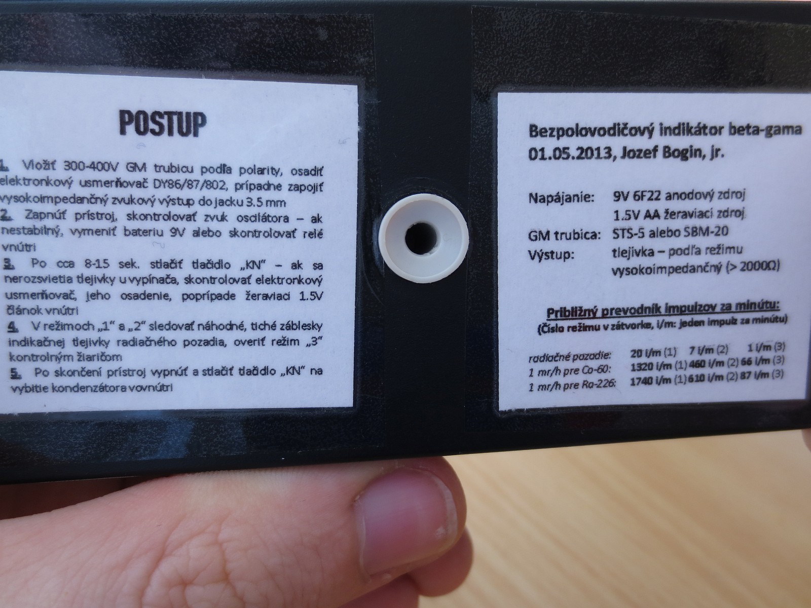
As stated on the back of my device, background radiation produces 20 CPM on the first range, 7 CPM on the second and just 1 CPM on the third. If the Geiger tube is in its correct voltage range, information from datasheets can be utilised: 29 CPS equals to 1 mr/h calibrated for radium-226, and 22 CPS equals to 1 mr/h when measured against cobalt-60. This applies for SBM-20 (STS-5) tubes only.
 Schematic, click to enlarge
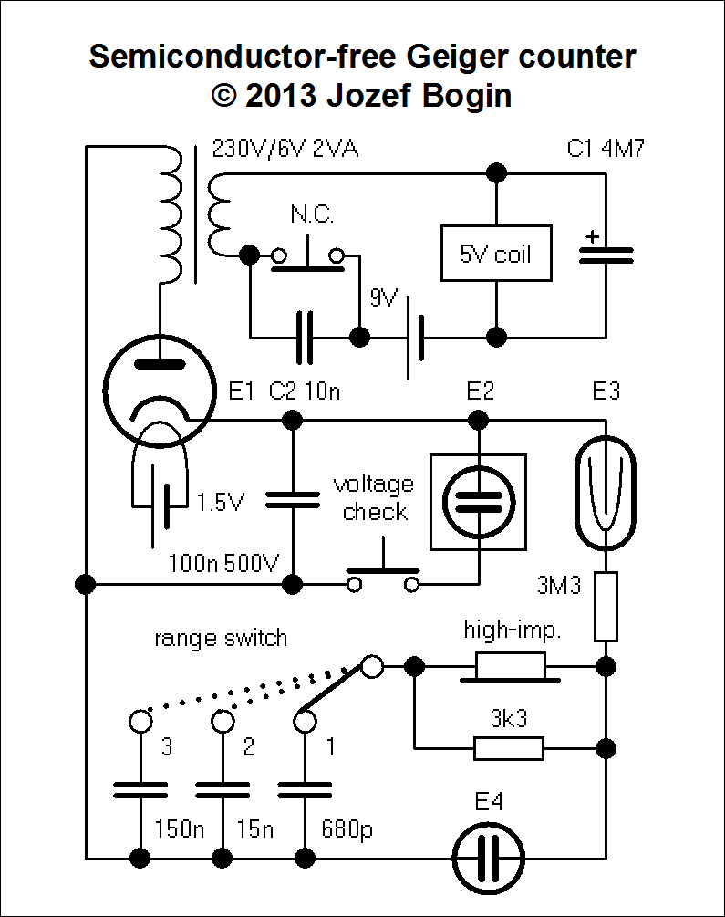
Last but not least, the schematic of the guts. Well there’s a reason why its on the bottom of the page: it won’t plausibly work for you without previous experimentation, unless you used exactly the same parts as I did, including the inductances of the relay coil, transformer coils, glow lamp characteristics etc. For this reason I’m going to provide what exactly you would be interested to tweak.
C1 forms along with the relay coil an LC circuit. Generally, the lower the capacity the higher the switching frequency (and thus lower the voltage, unless you hit the resonance). Tune this in a range between 4.7uF and 47uF to get the desired output. In some cases, you might want to fiddle with the filtration cap if the output voltage is too low (or too high), although it’ll cause more ripple.
Personally I do not recommend using those regular 12 volt 10 amp relays as they tend to die fast in this circuit. If you plan using them, better make yourself a socket for easy replacing 🙂
The one I found to work the longest was a small one with a five volt coil, unknown brand, orange color, desoldered from a PCI faxmodem. With a 4.7uF capacitor and a 6/230V mains transformer, it runs on a frequency of 480 Hz and provides over 400 volts dc (tweak the filtration cap).
Which non-semiconductor rectifier to choose (E1), had been talked about above.
C2 helps to quench the arc on relay contacts, thus reducing wear and prolonging life, just like in old cars with breaker points. Which capacity to use is again dependent on your relay, might be between the interval of a few nanofarads up to a few hundred.
I’ve soldered in this part the last, when it was all tuned so the inverter gave enough voltage for the Geiger counter tube. You know you have found the right capacity when the output voltage increases a bit with it, and you notice a slight alteration to the clicking sound.
E2 are two NE-2Hs in series with a third starter bimetallic glow lamp made by Czechoslovak TESLA, itself with an ignition voltage of approx. 180 volts dc, all totaling 360 volts ignition voltage (90+90+180).
A Soviet SBM-20 (a new version of STS-5) was used in place of the Geiger tube (E3). Found one in a drawer along with my other components – works all right.
E4 is a small NE-2H.
For “ranges” 2 and 3 you might use classic 32 ohm headphones, but generally vintage military/ham 2000-ohm cans are preferred, since there’s no amplifier present.
To reduce buzz in headphones, ground everything to one single point, thus avoiding ground loops. If that does not help, try grounding the transformer core. Since the oscillator runs on a low frequency, there will be always noise because of the ripple.
And that’s all, folks; if you like, comment and share. I know it’s technologically backwards, fragile and power hungry – draws 675 mVA from 9V and 1.5V combined – but it has been a nice experiment in today’s world of silicon, even though without the imminent danger of a nuclear strike, whose EMP it’d certainly survive.
Hello dear sir. How are you? I am posting this comment regardibg a question I have. Basically, how would I go about modifying the circuit to use a vacuum tube for oscillations instead of a relay? (What oscillator type, etc). Thanks in advance
one more update
all the tubes have been orderd
and now i am gonna build it soon
http://imageshack.us/f/28/p8q.png/
Immediately the next day after posting this, I’ve found a schematic from a Holland DIYer with his own design:
http://www.gloeidraad.nl/radioforum/index.php?id=147164
Hello
Robot797 here (from that forum and YouTube)
I see that you found my circuit
I was just about to ask you if you think it is any good
I drew it just to see if i had the knowhow
By the looks of it, your circuit is going to draw at least a single amp from the heater supply (almost two times as mine) – not including the 12V supply – and it’s going to be a little bit more fragile, too.
On the other hand, you might achieve a longer lifetime of the inverter element (a relay coil might die sooner than a filament in a vacuum tube).
True but i know that D cell batterys last a long time for the filaments
And i am convinced i can make the power supply with one tube instead of 2
Yes, a single stage flyback topology can be done with a single active element.
D cell for the filaments is a good option, although it ceases to fit in your hands then 🙂
Yea i know
But i don’t really care about size
But i will cast it in acril
hello
i have redesigned it for a flyback configuration
http://img716.imageshack.us/img716/9564/geigercountercircuit2.png
can you give me feedback
Should work, keep us posted about the results 🙂