Now, let me begin this article by stating that this *is not* a so-called “conversion” with an LM317 (or any other linear regulator in general) like you might have seen on thousands of other web pages, nor a so-called “lab” supply that was made just by shorting the PS-ON pin. This is a real ATX to regulated supply conversion, which might come in handy for you.
The reason why I have chosen to make this article was the increasing number of popularity of my ATX supply hack, which I posted on 4hv.org and simultaneously on Youtube in August 2011. A lot of people started to ask me for a schematic, however I had to respond that there was no universal one. For every different kind of supply the approach is the same, however parts involved might differ a bit.
The resulting product will be a smoothly regulated ATX supply from circa 4.7V (some even might go down to 3 volts) up to the voltage you set it, with short circuit protection intact and with maximum output current exactly the same as it’s written on your original +12V line rating ! So, here is how to do it.
 No LM317’s and no huge heatsinks…
To change the output voltage of a power supply like this, you need to alter the feedback (PWM) circuit of the driver IC. This tutorial will be regarding those supplies, which are of halfbridge design (two high-voltage NPNs on the primary) controlled by a TL494 chip, or its Chinese equivalent like DBL494, KA7500 and alike. So, if your particular PSU is equipped with a chip like this (a majority of ATX PSU’s in the 200-400 watt range are), read on. However, there are also a few other designs, such as single MOSFET flyback topologies, with optocouple feedback driven by a UC384x chip, which this tutorial does not cover.
Step 1: After you have disassembled your particular PSU, double-check that the TL494 chip is getting its supply voltage from a “helper” supply. Basically, you should see at least 3 ferrite transformers on the circuit board and a heatsinked linear stabilizer (78xx) powering the chip. If you do not, it is not advisable to proceed. As far as I know, AT supplies are built this way, so take caution with these.
Step 2: Locate the TL494’s first +IN1 pin and carefully disconnect it from the circuit board. Use a desoldering pump or nipper pliers, the choice is yours. Then, make a circuit like this – the values specified are good for a start; you might have to tune them a bit for your setup. Wire it all up as shown.
Step 3: After you are finished with step 2, this is important: set the tuning potentiometer P1 so it shorts TL494’s first pin with the former +12V line. Use the former +12V as output, ground stays ground. Plug the supply in and turn it on with a voltmeter between the +12V and GND terminals. If it fails to turn on, proceed with step 4. Otherwise, start slowly increasing the output voltage with the potentiometer until it reaches 15-16 volts. Use the trimpot P2 to limit the maximum voltage to 15-16 volts; until the tuning potentiometer won’t let you go past this value. After this, try some dummy load. The supply should have its short circuit protection intact (try it) and should give you the same amperage rating as it was on the former +12V line. If the supply shuts down even under a light load, proceed with step 4, otherwise – add a transil or a few watt 20V Zener diode in reverse polarity across the output terminals – bravo, your regulated supply is now finished !
Step 4: If you are instructed to proceed here, unplug the PSU, fast. Double-check the circuit you have made in step 2 and whether you have wired everything properly first. If it seems to be order, trace the former +12V, +5V and +3.3V lines for any fast or sensor diodes, or low-wattage Zeners, which might lead to the overvoltage circuitry. Desolder always the first diode which you might meet on each line, then repeat step 3. If this did not help and you are sure that you have not missed any, here’s the last resort: disconnect the 4th pin of the TL494 and ground it through a 4k6 resistor. Alternatively, chip off pins 13, 14 and 15. This way the supply will force power on regardless of the protection circuitry or the status of the PS_ON pin. You are going lose the original short circuit protection this way, too. This is where the fun begins: now if you make a mistake or a short circuit, be prepared for some fireworks. At this point I also advise you to cover the supply with a hat or something before powering up. 🙂
A note to add: if you manage to break the feedback circuit, the output voltage might skyrocket up to 30 volts, destroying all electrolytic capacitors and other parts in the process.
And that is about it, folks. Congratulations if you got your supply working this way. If you didn’t, don’t be sad – for some supplies this conversion just might not work at all. In addition, ATX supplies are not something scarce, so get a few to experiment. If it tripped the breaker and burst in flames, then I hope you have read the Disclaimer before attempting this conversion, as you were instructed to do so at the main page. 🙂
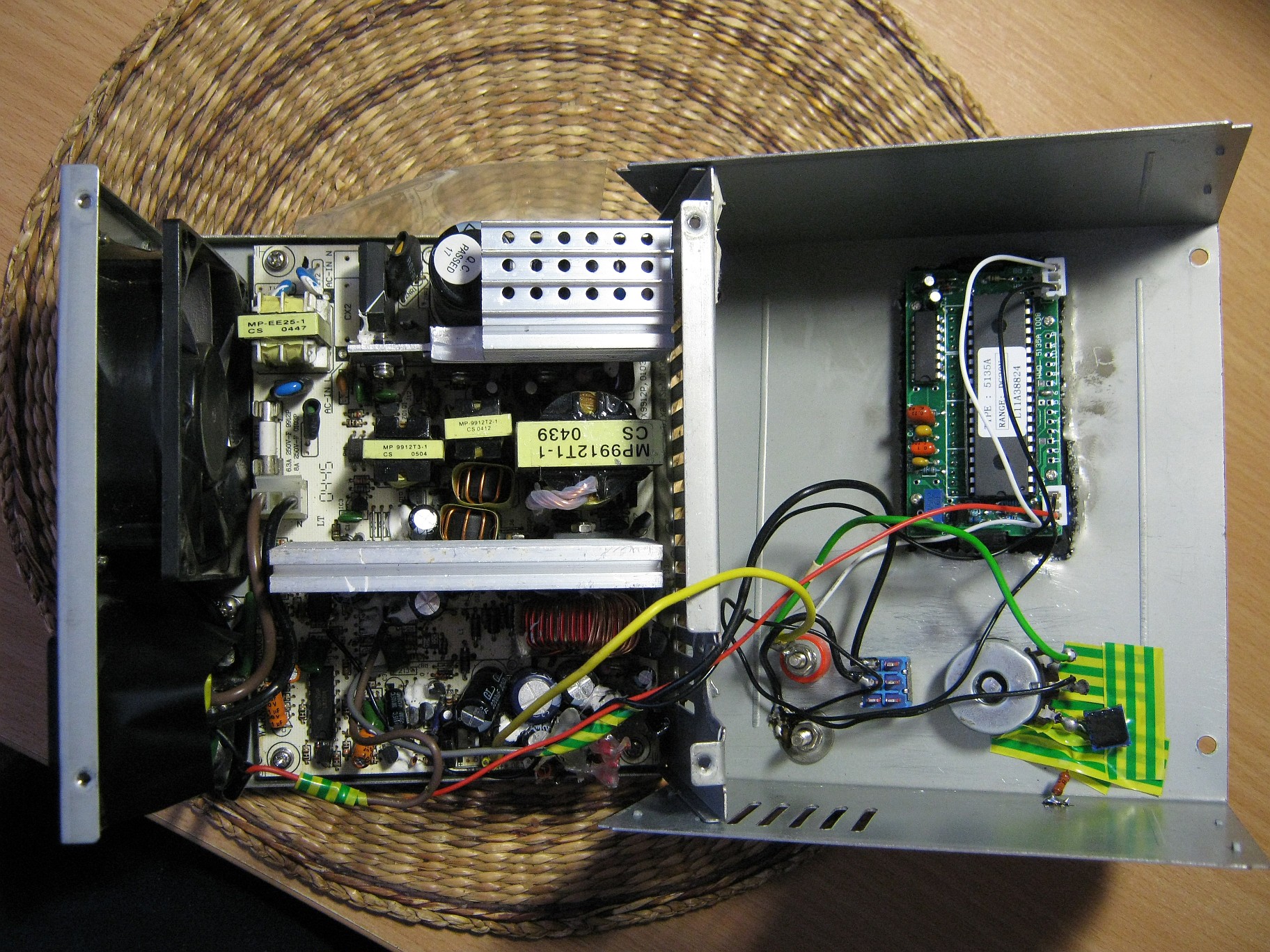
This is the conversion applied to a 300 watt “DTK” supply. As you can see, the output stays stabilized – even at a 14 amp draw, the voltage drop is just a few tenths of volts. However, I forgot to include the protective transil/Zener described above and managed to short one of those internal Schottky rectifiers in the PSU, from inductive kickback caused by a cordless drill motor.
Dekuji Pepino za napad a vysvetleni, proc nemuzu cinsky zdroj “sjet” az na nulu.
Je to zrejme tim, ze stazenim napeti, nebo proudu k nule, ztrati ridici TL494 napajeni a padne. Moc Ti dekuji…..
Jeden takovy moravak 🙂
Vďaka Jozef za dobré praktické rady.
Ďakujem 🙂
Hi. I have a Thermaltake, Toughpower 775watt xt. Using ics ps229 and the controller is a 6800g. Only needing 13.8 volt for ham radio use and 12volt for several cooling fans .have you any ideas? Unit is on bench and have removed the 3 and 5 volt boards. Thinking the neg.12v.would be fine for the fans. Only using two of the 8 inch ones. Ideas? Came out of Cooler Master tower. Thanks . Robert, KD2QDC
Robert -KD2QDC. I HAVE A 775watt Thermaltake Toughpower XT. . The on ic is a ps229. The controller ic is a 6800g. Can this conversion be accomplished with this particular supply. Only interested in say 7.5 volt to 13.8 volts??
Did you know that you can connect 2 computer power supplies in series?
You only need to make sure that your DC ground is isolated from earth ground by placing a plastic spacer instead of the original screw that normally connects the PCB to the case… Then you can connect 12 volt (yellow wire) from one psu to the ground (black wire) of the other and when you measure between the 12 volt of one psu and ground of the other you’ll see that you have 24 volts…
But it gets better even, when you connect 3.3 volt or 5 volt instead you will have the following voltages to play with: 3.3V, 5V, 6.6V, 8.3V, 10V, 12V, 15.3V, 17V and 24V
I’ve done it myself and still use the 2 psu’s whenever I need.
6105b
I have Sc5601b ic will this mod work for me
Whilst I admire the approach taken and the attempt to aim it at people who desperately want to spend a minimum amount (ideally nothing) on a BENCH supply (variable volts, realistically without MUCH need for more that about 5-10 amps complete with current and voltage protection) I think the approach of using an EXTERNAL boost circuit for the variable part is probably more time effective if not cost effective.
The price of many DC-DC converters now from eBay, BangGood, MiniInTheBox and others plus the price (or lack thereof) for really good and accurate LED volts/Amps displays is such that one would be better off using an external boost circuit and feed it with the standard ATX 12V rail, especially if the supply is a more recent one intended to supply modern MoBos as there will be plenty of Amps available from it.
A circuit such as this one
http://www.banggood.com/600W-DC-DC-Boost-Converter-Step-up-Module-Mobile-Power-Supply-p-88973.html
can produce a FULLY variable voltage from 12v to 80v off a 12v rail input for around £11/$13/13€ this will hardly break the bank for most people. A decent case can be made from a sliced and diced old PC case and with some clever Dremel cutting could make a great looking unit with the existing rear supply position kept for the ATX PSU. The fixed 12v, 5v and 3.3v rails can be brought out to banana sockets via separate voltage and/or current meters – they are only a few bucks on-line. 0.28 LED voltmeters can be bought for less than $2 post paid (also from Banggood). Such a design has a LOT more advantages that modifying an existing working supply to something one can easily blow and of which the final specs are unknown or uncertain without testing, which could easily negate all the work
Out of curiosity, would it take much to add current limiting control?
See my later comment above
Thank you for explanations in this forum, they helped me greatly. I convert succesfully many ATX, from 300 to 600w with TL494, DBL494, KA7500, WT7520, SD6109, SG6105A chipset and got from 15 to 29amper on 12v regulated rail. I have on my hands an Coba Nitrox 750w PSU with CM6800G chip and i tried to convert it for more amps but unsuccesfully.Thermaltake,Corsair have the same PFC circuit & chip. Do you have any idea or knowledges how can I do it ???? Thank you in advance.
Excuse me, but I cannot understand where exactly to connect potentiometer (which pin of TL494) . To pin 1 (IN+) , pin 2 (IN-) or someone else. Thanks’ in advance.
Pin 1. The original schematic had it named “REF”, sorry – fixed that.
HELLO I want modify a power supply the ic is sg6105a please help me I don’t speak very English but it’s not a problem I use Google translation thank for you.
For the guys that want a higher voltage output from an ATX SMPS. I have a question.
1. The large transformer has a center tapped primary winding. If you rewire the transformer binding post to power just one set of these windings. This should result in doubling the output voltages, so make sure the caps & the control zener diodes are changed prior to applying power…
2. The large transformer can also have it’s secondary windings rewound. More work, but even higher output voltages can be obtained… PS – I’m presently rewinding a transformer. Ha! Ha!
Has anyone tried this conversion???
Wow, you are game – pulling off transformers, rewinding them (and all the work associated with that) and then replacing them, along with all components that could be affected! I sounds like it might be easier to just build a supply to do the job you need.
Just finished preforming your mod on a NIPDA – P4-550W ATX SMPS. It had a SDC 7500/339 controller. I removed the original feedback jumper to pin #1. I relocated the grounding resistor to ground the feedback circuits. I then installed the P1 wiper leg to 7500 Pin #1 side of the original jumper and the needed ground was picked off the grounded side of the grounding resistor. Thus I did not have to cut into the circuit or pin #1…
Your circuit worked great after I changed to a 5k trim pot & a 5k fixed resistor… The 12VDC rail provides 5VDC to 14.56VDC and the 5VDC rail provides 2.5DC to 5.85VDC. The 3VDC rail is feeding a current controller to power LED & Laser diodes…
I’m using the -12VDC line to run the 12cm fan with a temp speed controller and to power the digital volt meter thru a 9V Zener. The 5VSB is powering a constant speed 8cm fan…
All the output caps, the inductors & Shockley Diodes were up-graded &/or installed. Plus I added an input line filter…
This was the third ATX internal variable voltage supply. Number two died when probing the primary side while energized. Nice arc, but it is now working again after replacing the 5VSB primary active components…
Hi and thanks for sharing your experience; glad you got it working 🙂
i have the same sdc7500 and 339 controller (my psu is a 400w) , but can’t manage to make it working with high current.
could you please provide a picture or drawing?
my psu shuts down if the drill draws to much current. if i slowly start the drill its fine, but if i try to jump from 0 to full power the psu shutsdown. until i turn it of and on again.
i dont understand exactly what you did. “removed the original feedback jumper to pin #1…”
what? which pins did you ground?
is it posible to get a larger voltage ranges without jumping the protection circuit? aka reaching 35v for example?
Hi, I’ve recently modified my PSU. It starts and regulation works up to 15,6V, the same with dummy load, but there is a problem with the low voltages, without any load it only goes to 8.2V and if I try to go lower it turns off and I have to reconnect the green and black cable. When I connected some load to it, the “turn off voltage” changed and i could go to 6.2V. When i try to turn on PSU with voltage set under these values it immediately stops working. It looks like a short circuit protection turns it off. With multimeter connected to it, when i try to run it and voltage set under 8V for short moment multimeter shows the value set by potentiometer but at the same time it drops to 0. Sorry for my english.
Hello,
Having same issue as your. Maybe you managed to find the solution?
By the way, my ATX circuit looks like this one:
http://electro-tech.narod.ru/schematics/power/comp/codegen_cg-07a.gif
I have a 400-Watt ATX SMPS with the ATE2008 chip. Using a 5k trim pot to set max high volt (14V) on the 12v line and a 10k pot in series, to adjust the voltage. These were attached between pin #1 & ground, after the original voltage trim resistors were removed. This allowed me to adjust the 12V line from 14V to 6.75V… If I wanted a lower voltage range I switched to the 5V line…
BTY – I also removed the Optical Controller trim resistors and replaced them with a 5k trim pot. Still playing with this, but I’m assuming I can adjust the current/voltage limiter. I also upgraded the 12V line diodes to 40A 100V with higher voltage & capacitance on ALL the output lines. I’m adding a small 5V cooling fan on the 5V control circuit… NO smoke yet, Ha! Ha!
hello , i did one following the exact instruction on this web site, everything is working perfect fine , i do have a small issue, it does start @ 4.99v with no noise, when i do start to increase the power it’s start with a buzzing noise like a high power transformer , and the noise increase with the power,i should worry? it does pass the test of light bulb, dc motor with no problems
ok…now something strange …it seems that 5v rail is variable from 0 to 5v….on the 5v rail i have a dummy load of 10ohm 10w from the first hack of the atx and the sound is comming from this rezistor i think…:( i’m confuse….help 😀
ok…i did remove the rezistor and the sound is still pressent….i can’t see what is wrong 🙁
The sound is coming from transformer due to chips in output square wave. Being higher frequency you’ll hear it.
Your wires actually pick up the harmonic EM field (probably offset-ed EM field from chokes or transformer) and it pulsates on pin 1.
Remember that Pin 1 and 2 are inputs of the comparator and comparator itself is actually an amplifier, so your pulsation on pin 1 gets amplified and fed into the output transistors.
Thus, use shielded cable to connect the potentiometer and use the same shield to connect to the potentiometer’s case as well as ground shield closest as possible to pin 1.
Hello Jozef,
thank you for sharing this amazing article. I´ve made this modification on some PSU with sucessfull.
However one thing I could not solve. My ATX goes from 2,4v to more than 16v.
I would like it could start from zero volts. The ATX has an KA7500B PWM controller. What kind of modification should I do?
I really would appreciate if you could give me a direction.
Thanks in advance.
Regards,
Henrique
Unfortunately, I don’t think that is possible.
Regards Jozef
Thanks a lot bro
Thank you very much! Your post was very helpful and I successfully converted a KC-235 ATX power supply which had a DBL494 chip. Just needed to solder out two resistors (R15 and R16) which originally went to the rails from pin 1, then soldered a long jumper wire (originally for plug-in breadboards) to the pad of R16 which had a PCB trace connection with pin 1. Then I lead the jumper wire through the vent holes, out of the power supply, so I could even use my plug-in breadboard to test some resistor values and how they regulated the voltage.
The only bad thing is that my supply is one of those which only go down to 4.8V. I was thinking, can I play a similar trick with pin 2 which is the other input of the error op-amp? I guess this pin should always be at 4.8V. So maybe I can replace some resistor with another one to get a lower minimum voltage, say, 3V, by changing the potential of pin 2 to 3V? The problem is, the schematic is quite complicated. (http://www.hobbielektronika.hu/forum/getfile.php?id=104135) Can you perhaps identify some ways to hack the lower bound on this particular model (and, maybe, other similar supplies)?
Thanks a lot for the useful information! I just converted mine and it works great! The lowest my unit will go is 5V and the highest is 14.45V before it shuts down in protection mode so I set the maximum to 14.4V.
I connected the fan to TL494’s pin 12 Vcc so that it would always spin because as it was it would only start spinning at around 8V.
I uploaded a video on youtube of it: https://www.youtube.com/watch?v=yBqei0f0mNI
And here’s a couple of photos: http://s10.postimg.org/95x9v4r3t/PICT0009.jpg
http://s10.postimg.org/wvmpjtph5/PICT0011.jpg
Really cool!
Hi Jozef,
You did an amazing job, congratz !
Well, I tried to do the same with an old 300 W PSU and I used the same components as you.
The main chip is a DBL494, so all went fine.
But the max voltage is only 10 V and the lower one is like 2,5 V 🙁
What should I do ? Can you help me please ?
This is a great idea! I’d like to get down lower than 5V (say 4.0) any ideas?
Some supplies allow you to go as low as 3 V.
The issue is that the TL494 is powered from the DC output voltage. When the output voltage drops too low (around 5v) it stops functioning. The solution is to power it separately from a small DC power supply. Then you can adjust the output down to zero.
is it possible to do something similar for the -12V supply? I have a very specific application that requires
+5V, +13.2V, and -15V and using an TX SMPS would be perfect. So is it possible?
Nope, the -12V is a separate tap and usually has a maximum current rating of 500 mA.
Atx variable from 1.8v-20v with tl494 and lm 339,I found it on a web site and it works.
They had use only a 50k pot mount on pararel on 12v rezistor feedback.
which website???????????
What to do with LM393?
I have a similar atx like you,tl494 and LM 393.
Však píšeš, že si to urobil od 1,8 V do 20 V. Tak prečo sa pýtaš, čo robiť s LM 393 ?
Quick question. is there a way to make it 18v only. I need it to run 18v only. no need to change the voltage. it could also be 16v
Yes, use a trimmer instead of a potentiometer, then set its resistance so the supply runs on 18 volts.
Don’t forget to replace those caps, which are 16 volts rated.
Regards Jozef
How does this mod affect the 5V rails?
Hello
I need help regarding your scheme. I have follow your text step by step and all I get is 15V without option of small value of 15V.
What is also strange if I disconnect yellow wire (ex. 12V) voltage didn’t change stay 15V, I have try various option to add trimmer resistor on any side (all combination) but nothing 15V stay and don’t move.
Any tips.
Thanks & Regards
Hi Jozef,
Thank you very much for the article.
I have a question about the transil, which V do you recommend, and Bidirectional or uni?
Thanks.
I’d try an unipolar one, say from 30V and up? There might be a better approach to this though, but personally I wouldn’t spend any reasonable amount of money for tampering with ATX supplies. Use whatever is at hand 🙂
Thanks again Jozef,
The MOD did not work on this particular PSU, under any load it would reset to 0v.
However I did what user “Fleck” did (a few posts down) because I have the same WT7510 “POWER SUPPLY SUPERVISOR” chip.
So what I did:
Disconnect pin 7(Vcc)
Disconnect pin 3(FPL_N) AND connect it to Ground.
Now I have a perfect working 2.5v ~ 15v, under heavy load no problem at all, load regulation is excellent!
So thanks to Jozef and Fleck 🙂
Hello
I done all that you have write. First I get some strange noise inside supply then when I connect bulb 5W supply shut down.
What I have done wrong?
No, you haven’t done everything I wrote in the article. You skipped the fourth step, to which you have been referred to in the previous ones, in case the approach did not work.
hello
Great guide thanks. If i short pin 4 to ground over 4k6 resistor do I still have over current protection or do i lose it?
The “hacks” to force power on of the PSU described in step 4 make the driving IC run till mains power is disconnected, so you’ll lose the overcurrent protection.
Use this as a last resort and install some kind of a circuit breaker or fuse in series with the output.
it works thanks
Hi, Awesome job on hacking this ATX power supply! Loved your tutorial. I have Corsair TX650 power supply which I want to convert. Is it hack able?
http://www.corsair.com/en/power-supply-units/tx-series-power-supply-units/tx-series-tx650-80-plus-bronze-certified-650-watt-high-performance-power-supply.html
Thanks,
I don’t see a reason why it shouldn’t – if it’s got a TL494 or equivalent you can follow this tutorial, any other chip would need a different approach however nothing is impossible..
I required a 16V 10A supply for a model train DCC booster.
This setup works a treat. 🙂
Initially I had to disable the zener diode associated with the 12 volt rail and replaced it with a 20 volt one.
Well done, this is an excellent hack. 10/10
Regards,
Relayer
My PSU has an 7500, i did the process but I get just 8 V max.. what could be wrong?
Hi, I did the mod adding an internal switch so I go from ATX regulated with it.
Thanks a lot for the hack!
Excelent solution for this entreteinment, the simplest regulates power source I saw. I need one for a foam cutter, this is other story.
I do not know to much about electricity/electronics, but, can you tell me what happend if I choose the -12 V cable instead of ground? Can I do that?
Best regards
No, using the -12V will not work, you must use ground.
Regards,
Relayer
hello i got a 400 watt power supply with a WT7514L
http://www.datasheet4u.com/datasheet/W/T/7/WT7514L_Weltrend.pdf.html
is this one hack able ??
i was looking for this finally fond this one
i was playing to make a lab power supply but its getting heavy and needs good cooling this can do it with out getting loud and heavy
waiting for a reply
thank you
No, the WT7514L type IC will not work unfortunately. Its designed to provide PSU protection, power good output and protection detection.
Regards,
Relayer
Thanks for the great tutorial, i have succeeded to convert an atx supply by following your tutorial. thanks.
Glad you like and congrats 🙂
By lifting the Pin#4 of …494, short circuit protection is also removed. So this may fires transformer?
hi, great tutorial here, just one question, if i want to go upto 24 volts with this mod, will i only replace the capacitor or should i also replace the zener with 24v zener?
thanks
In theory yes, but you ought to try up to 15-16 volts with your particular supply first.
Great tutorial by the way. It is very good.
I have found a way to keep the protection ….. just remove the diode betwin pin 2 and control and put a trimer or a 47k potentiometer with midle pin to pin 4 one pin to 4.7k resistor to ground and other pin to control.
Great tutorial Jozef. I easily managed to get a very old and simplistic ATX converted. However, I’m encountering a weird problem with a newer one, the Antec SP-350. The issue is this: the adjustable output is fine from 2.5-4.5V, but as soon as you hit 4.5V, the supply shuts down and must be disconnected from the mains to reset it. Any idea what this could be?
I bet theres a Zener in reverse polarity parallel to one of the lines (3.3v, 5v, 12v), find them and get rid of them. Sometimes, desoldering those 100 ohm 2 watt resistors off 5 and 3 volt lines helps.
Regards
Sounds like you have a voltage supervisor, check this schematic:
http://danyk.cz/s_atx01p.png
If you have a WT7510, LP7510 or any other alternative… this is most likely your problem, that chip turns on on about 4V and detects under voltage fault and turns off TL494. What I did to bypass WT7510 chip:
Desolder & disconnect at least 3 pins: pin 8 (PGO), pin 7 (VCC) and pin 3 (FPL_N/FPO), now, solder Standby 5V to PCB where PGO pin was soldered (pin 8 disconnected, solder standby 5V in that hole instead of pin 8)
solder GND where pin 3 was soldered (pin 3 disconnected, solder GND in that hole instead of pin 3)
Everything else goes from this tutorial!
Meh, trying my best to explain, hope you understand! If not, I’ll make schematic for you!
I am not sure about short circuit protection… as PSON is NOT working!
Sorry, I was wrong, did not checked, just guessed – the WT7510 VCC is from StandBy 5V, so must be a range of PGI, or voltage comparators, when 4+V is on 12V rail (dunno, 3.3V, 5V or 12V, or PGI gets detected first), but the principle is the same anyway. I just desoldered VCC and grounded pin3, no need for standby 5V to pin8
In your diagram why do you show the centre and right leg of P2 joined together?
Thanks
I always do it with pots in a variable-resistor configuration, as it helps to reduce the “crackle” of the taper, resulting in instabilities especially when the pots are old or used extensively (80% of my parts are salvaged desoldered)
Hello Jozef.
I’ve found a collection of Power supply schematics. I think it can be useful. It’s .
I own an ATX power supply with an unusual DR B2003 (marked as 2003) feedback regulator. PCB is exactly the one shown in that schematic collection page (simply search for text “2003”). PCB picture . My PS is labeled LC-B350ATX. So shemathic should be very close to 250W one.
Now, do you think I can try your mod using pin 14 of 2003 IC?
Thank you,
Willy.
Have you tracked down the datasheet on 2003 yet, I have the same problem, its like they dont exist…
regards Chris
Hello Jozef, I have a PSU with chips I’ve not seen mentioned in your article and I wonder if they are suitable for your elegant power supply hack.
DNA1001D which I belive is power factor correction controler + PWM (similar to UC3842)
DMA1002D intergrats several “housekeeping” functions such as current limit, output sequencing and OVP.
LM324N low power quad operational amplifier.
info from this thread: http://www.badcaps.net/forum/showthread.php?t=1229
Thank you for any help you can provide.
Joseph
Whoa, now those seem to be real exotic chips.
Unfortunately I haven’t met with them yet, so I cannot provide any practical information than those readily available in data sheets.
It’s up to you to experiment – if you are able to tweak the PWM, you should be able to alter the output voltage ranges. Needless to say – in case you obtained a good working result, don’t hesitate to share it 🙂
Best regards.
The old power supply is doing nothing useful so I might as well give it a try. Thank you for the reply Jozef, if it works (or not) I will post my results.
I did another one from and old AT PSU but when I incorporate the trimmer and potentiometer the output is only 4.5 volts and can go as low as 1.7 volts on the 12volt rail but when I disconnect it give me a full 12.07 volts and when I connect the needed 12+ to the 5volt rail it raises the voltage to about 8.7volts from the 12volts rail.
this unit is using TL494 but behaving differently from the earlier one I made. can you enlighten me on this.
thanks and more power to you.
Firstly try powering the TL494 from a separate supply, ATs lack a helper supply for the chip (only two ferrite transformers on the PCB are usually present).
You could always try inspecting the five volt rail for any load between it and ground, keep it unused.
Best regards.
I ve tried some mods, with adding some resistors between the 5V and 12 Volts, but they all didnt work.
Your mod is great and simple. Very good !
Thank you,
73,
Tom, DG6EK
Worked fine great idea… I like the built in protection…. hats off to you…
Eureka! It Work’s!
Had to disconnect the protection circuit though.
Extra in-line fuse should do the job.
Tanks for sharing.
Hi Josef,
Nice work and thanks for sharing.
The mod works perfect in a Trust 16116-02 PSU.
But, now the former yellow cable is variable, so I need an extra fixed 12v output to power the fan (and the Voltmeter).
Where did you get an extra 12v line in your prototype?
Regards from Spain.
Fernando
Hey Fernando,
I’ve connected the fan to +5VSB, to keep some air circulation inside the case. However, you might aswell tap TL494’s supply through a 7812 or a similar stabilizer, if 12V would be really needed.
Best regards Jozef
Thanks Josef!
The TL494 VCC is perfect.
Regards
Fernando
Nice, but very messy work.
Agreed, I’m quite a gadgeteer. 🙂
Hi, nice job on hacking this ATX power supply! Loved your tutorial. I have 2 old power supplys witch I want to convert, I’ve already converted one successfully. I’t had a TL494 chip and I used a 10 turn potentiometer so I can regulate it very accurate, it goes from 2,34 up to 16,75 volts.
As for the second power supply, It is a Asus gps-300ab and has an DWA105N161 chip, for which I can’t find any data sheet. I think it is a Chinese version because when I Google it, I get all kind of Chinese stuff. It seem the have two ferrite transformers. Any ideas? Of course I can just try it, but I don’t want to blow it up, if it can’t be converted I like to keep it as a non regulated power supply.
Many thanks in advance for your reply.
Hey Pieter and congratulations you got it working.
If there are no datasheets to be found and Google spits out chink links, you might be searching for a serial number (rather than the part number itself), which they have in some evidence – this then gets copied by a script to millions of other “wholesale components” websites.
If it’s a TL494 equivalent,or a similar driver with 2.5V Uref, you’re good to go. However, some chips (as discussed below) do have some *internal* overvoltage bullshit inside them, so if you stumbled upon such protections you’d need to fake the correct voltages, with Zeners and such.
Best regards and good luck.
Hi Jozef,
Nice mod you did! Congrats for it! Your hack is today on Hack a Day!
One question: You mention to replace the capacitors for a high voltage ones to increase the output voltage up to 24V. In this case the Zener across the output pins should be it’s zener voltage higher to 24V, is it right?
Hi and thanks for your comment – yap, noticed the inrush of views.
Yes, one needs to adjust that Zener appropriately after the mod.
Superb work you’ve done. All I seem to find around the internet are people who route the voltages of an ATX PSU to binding posts and feel like “omg I hacked that psu”. No you didn’t, anyone with half brain can do that. Fewer are the ones who actually go through the “hassle” of throwing an LM317 in there – certainly useful, but still not hacking, just adding circuitry. That’s much different from going through the hassle of actually understanding the circuit and modifying it to do what you want – that’s hacking.
I have literally a dozen AT PSUs gathering dust here, so I’ll probably stick to ATs for a long time. Opened two of them; one has a XXX494 clone (forgot exact part name) and power-good circuit made using discrete transistors; other has a DBL494 and power-good made using DBL339 quad comparator.
I guess the main disadvantage to ATs, compared to ATXs, is their lower rated current at 12v, so I’ve been wondering how could I overcome this. Since current on primary is not very high, probably there’s no point in changing the switching transistors; maybe I should change the rectifying diodes on the secondary (i’ve identified two discrete power diodes and a 10A Darlington bridge; presumably one of these is for 5V and the other for 12V, no idea which is which) but then I don’t know how risky is it to overload the transformer. Another option: if the rest of my PSUs share similar circuitry, I may plug two PSUs in paralell by syncing their TL494s, but I’ve tried to measure voltage on some pins of DBL494 and it would go “bzzzz” every time I touch them with any of the (portable multimeter) probes, so maybe the clock wire going from one PSU to other would get so much EMI it wouldn’t even reach the other PSU.
I’ve been studying datasheets and schematics and I really can’t understand how TL494 is able to regulate simultaneously the +5v and the +12v lines using only one transformer. I’d think increasing the duty cycle on the primary would increase all the voltages. Or is it true what some say that only the 5v line is regulated?
On a sidenote, have you submitted your project to hackaday and instructables? Even though there’s no straight recipe for this mod, it will inspire and give general directions to many people.
Btw, there was no linear regulator at all. Only intelligent circuitry I could find was the DBL494, DBL339 and two small C945 TO-92 transistors. But since the 494 works with any voltage between 7v and 40v, I don’t see how this could be a problem; maybe I didn’t understand your warning about AT PSUs?
Hello and thanks for the comment!
Overcoming the current limit is described in the last sentences of step 4. Basically, it describes bypassing the overcurrent protection so it enables you to draw a little bit more current from the output if you have some proper sensing wired up, or at least a fuse if something should have went wrong. However most supplies are made of crappy parts, so it really runs on the edge even without performing such a conversion, so I wouldn’t really recommend that 🙂
ATX supplies do have a separate ferrite transformer powering the regulator microchip, 494 in this case. I can say I’ve tried this hack with an AT and didn’t succeed, it went down from 3 volts up to 14 and it refused to turn on afterwards. Bad luck maybe, I threw it out afterwards, didn’t really diagnose the problem on that one.
Yes, the duty cycle control messes with both 5V and 12V lines since the half bridge is on the primary side. In this conversion, the feedback is connected only to the former 12 volt line, 5V stays unused.
Haven’t tried to submit this neither to hackaday nor instructables but thanks for the tip!
On the other hand I wouldn’t want newbies performing this hack. Don’t want to be blamed if someone forgets to discharge those 350 volt electrolytics – some real crappy PSU’s lack a bleeder resistors for them – or gets the supply burst in flames because of an improper conversion.
Best regards.
Brilliant article, very nice achievements, you just summed up months of research. Keep it up, and great work.
Thanks, glad to hear 🙂
No problem,
I just wanted to ask about an issue, I manipulated a power supply but strangely I gives a snoring sound under load(especially when we disconnect ground from casing.) and while consistent under load its shuts down.
I think the overload protector shuts it down. Could we do some alteration to get more current without permanantly removing the short ciruit feature?
and note that the supply uses a TL494 chip and a quad comparator IC.
That snoring sound occurs at the lowest duty-cycle setting of your potentiometer and at normal conditions, it is usually faint.
What to do when your supply shuts down on load, is described above in step 4.
You are going to lose the short circuit protection only if the aforementioned diode-desoldering hack did not help and you still wish to continue with step 4 (doing the TL494 pin hacks).
will this power a 500 watt cb amp
Not at full power I’m afraid.
In your case I’d just use a mains transformer, properly filtered.
i ve demonestrated this circuit with my atx power supply , but when i started it it give me a strange sound , could you please attach some picture how to semonestrate this ???
i ve cut the attached pcb from the pin no 1 in the IC
then i ve done as the schmatics , but it give me strange sound like snoring
please help me
Check your wiring, confirm output voltages (as described in the article) with a voltmeter. Then, try a dummy load.
That “snoring” sound occurs at the lowest duty cycle and should be faint.
well i”ve connected the “tuned” PSU in series with a regular one, so i get the desired voltage and even more 😀 it needs more space but at least it’s still regulated 😀
Did you disconnect their ground connections?
Yup. I had to, because otherwise the two psu would have had the same ground. Now the “ground” of the second psu is the 12V output of the first PSU. The best part is that if i turn off the first PSU i still get the voltage from the 2nd one and vice versa, so i get either a 12-24V regulated PS or a 0-12V regulated PS. (:
Nicely done that way 🙂
Hi Jozef!
You have mentioned that you could crank the voltage up to 24V with different capacitors. Could you tell me which ones and with what parameters?
Thank you! (:
Basically, you will need to desolder those caps connected to the former twelve volt line and replace them with the same (or higher) capacitance rated at least 30 volts to have some headroom.
To be on the safe side I’d also desolder every electrolytics connected to the 5 volt line (not 5VSB though). Or, as said, replace them with a higher voltage rating.
Cheers
Thank you! Everything is working as a charm 😀 The only problem is that the PSU loses its ability to regulate the voltage above 20V. Under 20V the voltage drop is about 0.1-0.2V, at 24V, it is almost 4V with the same load.
… and is it the first pin of th ka 3511 that i have to use and how would i recognize it let’s say form the block diagram.
Greetings and thanks for your interest.
As for your particular PSU, I have no idea what reference voltage is used in it. But if you want to ry this, you’d substitute my 1st pin with pin no. 4 in your case.
However, as mentioned above, your chip seems to have some voltage sensing pins. You will have to disable this somehow, which is beyond me actually. Or, “faking” those voltages with appropriate Zeners might help.
Best regards
Great job dude, I know it’s annoying but can I use FSB250-60MDN-120(1)? it has 250W and a controller KA 3511 http://www.chipcatalog.com/Fairchild/KA3511.htm
Many thx
I have uc3842 in my power supply so pin I should use as you use?
As written in the article above, this tutorial covers only halfbridge TL494-driven supplies.
Hi! First of all, thanks for posting this great idea.
Buet before proceed with the same idea…I’ve got some questions:
1. I have a SG1605ADZ PWM regulator but I don’t know which pin I should use as you use the first pin in your power supply. In thin IC, the pin 1 is for the PS_0N so this is not the correct pin to desolder in my case.
Could you please check the datasheet of this IC and telling me which pin should I desolder to proceed?
SG1605ADZ Datasheet: http://www.fairchildsemi.com/ds/SG/SG6105A.pdf
2. Another question…Which kind of resistor and potenciometers should I buy? High power disipation? Normal resistors? Single or Multi-turn Potentiometers?
I’d really appreciate your help and your reply.
Many Thanks.
Hello and thanks for showing interest 🙂
As for your first question, unfortunately, the datasheet clearly mentions that there’s some over- and under-voltage protection circuitry *inside* the chip. Disconnecting or grounding those sensing pins – V33, V5 or V12 – might prevent the supply from starting. If this happens, try to override it somehow, or grab some 3.3, 5 and 12 volt zeners to “fake” correct voltage.
As for the conversion itself, substitute “pin 1” in my article for pin no. 17 in your case. The reference voltage of both TL494 and SG6105A seems to be the same (2.5 volts), so if you manage to break the original voltage sensing circuitry, you should be good to go.
As for the resistors, well, classic 0.25-0.5 watt ones will be fine. You’re not tweaking the output current directly, but the microchip’s duty cycle, which is at logic level.
These parts are run of the mill, i.e. nothing which you couldn’t be able to salvage from old electronics. My advice is: don’t buy every part, disassemble some old TVs or radio equipment and you’ll get plenty of these.
Best regards.
Nice text, thanks for sharing this with us.
Here is one schematic with SG6105 that might help in further experiments with this sort of supplies.
http://www.smpspowersupply.com/ATX_power_supply_schematic.pdf
Cheers