A spinoff of my previous MegaFDC project, this one targeting the “oversized diskette”: working with an ancient MFM/RLL hard drive, also known as a Winchester disk, under Arduino, “through” USB. Code name “Winchesterduino”. Quite a tongue-twister…
In action with a Seagate ST-225.
Boards, schematics and the source code can be found on my GitHub repository.
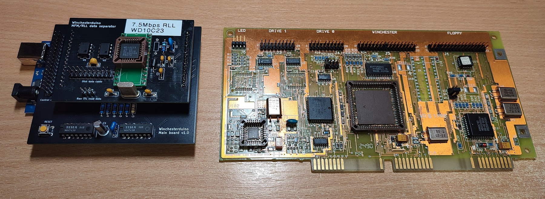
As in MegaFDC, the motivation was the same: grab an old PC controller card, a hot air gun, and try to make the chips talk to a modern machine via a cheap platform. The main controller of said card was the Western Digital WD42C22; these are also present in early ATA/IDE hard drives, e.g. the WD Caviar 280, Caviar 2120, and the like. They (or their copies) are still to be found in various “Far Eastern” marketplaces, and seem to work just as fine in this setup in both MFM and RLL, at standard data rates.
 Prototype boards.
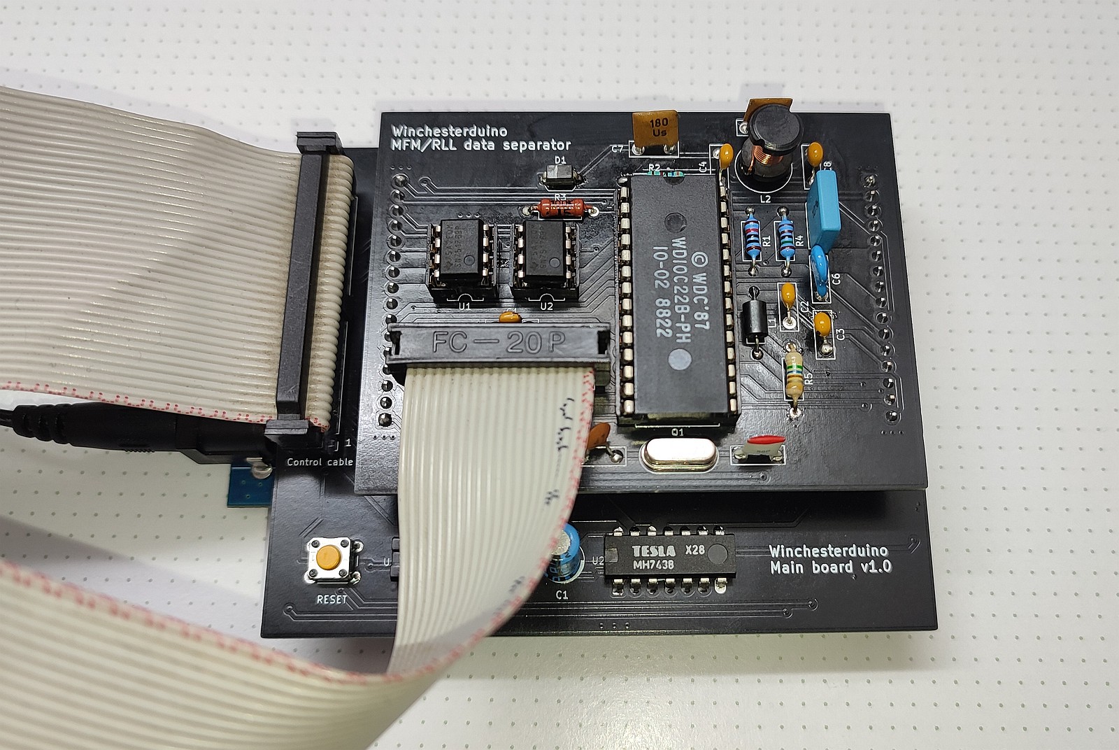
The main board fits on top of an Arduino Mega 2560, or clone.
A separator board plugs onto the main board, to be quickly removable for experiments with various data rates and modes.
Unlike a floppy drive controller chip in the MegaFDC, the data separator was not integrated in the same package as the hard drive controller. The ones that work readily with this WDC and can still be obtained on the internet, are the WD10C20, WD10C22 and WD10C23. The WD10C20 will only do MFM, but is also the cheapest (around 3 EUR a piece).
Needless to say, this project will also work without the controller and separator chips, in what I call a “minimal mode”. That means, with data decoding to be done externally, with a reasonably fast logic analyzer on the “raw TTL data out” connector.
 Separator chip desoldered from an RLL card and used in a cheap PLCC-to-DIP adapter.
Beware of the pinout, not all are 1:1. Mine had four pins switched for an EEPROM usage.
From a hardware standpoint, the circuits are simple. The main board connects the WDC address lines to an Arduino, and there are two 7438 bus drivers for the disk drive. These are required since the max. current of an ATmega2560 pin is 20 milliamps, whereas the “Seagate interface” of an MFM/RLL disk drive can draw up to 48mA.
Even though the WD42C22 provides a drive select output, I wanted the circuit to work also without the WDC and separator chips, so it is not being used. And, unlike an FDC, the head stepping is not done by the disk controller – I have to do it myself – so the buffers could not have been omitted.
The open-collector drivers of the hard disk require pull-up resistors on the mainboard side (R1 to R5). In addition, there are two pull-down resistors: R6 to keep the drive unselected during the startup of the Arduino, when its pins are at high impedance, and R7 to clamp the WGATE signal low if the WDC chip is not present. This is to avoid triggering a write fault signal that would also kill the raw disk data output.
A static buffer RAM for the sector data is required by the WDC. Since the maximum standard physical sector size is 1K, and we’re doing sector-by-sector operations, a 2KB SRAM is more than enough. I use a 6116 in DIP, it’s cheap and still readily available.
 Three identical main boards and three separator boards:
two identical ones for WD10C20, WD10C22 and one for a WD10C23.
12 volts bias through the Arduino DC jack is not required for the WD10C23 board, which omits the external VCO.
The separator board circuit can be plugged in any orientation into the mainboard. It is the “typical application” datasheet example: both WD10C20 and WD10C22 have a VCO circuit with a varicap diode, with +12 volts to provide biasing, supplied via the Arduino through its DC barrel jack connector. Do not forget this supply, as the separator will not read any data otherwise.
The varicap used in the WD schematics was an MVAM109, an AM radio tuning diode, and the bias at the cathode is around 9 volts. I’m using an Iron Curtain implement, a Tesla KB113, on both MFM and RLL with a WD10C22 successfully. A Siemens BB112 was also tested to work. I guess any similar varicap rated a few tens of picofarads at this bias voltage will be fine. Otherwise you can tweak the resistor divider.
Note that a WD10C20 will only work on MFM, and its pin 17 is always ground instead of an RLL/MFM switch. If this chip is used, I recommend setting its config.h define to 1 to keep the pin floating, or alternatively, cutting the traces to this pin on the PCB. Otherwise, choosing the RLL mode with this chip could short out one of the Arduino’s digital output pins.
Both the WD10C22 and WD10C23 separators supports both MFM and RLL, whilst the latter also avoids the VCO circuit and the 12 volts requirement. But the ’23 is more difficult to find.
As the data output of an MFM/RLL drive is differential signaled, similar to RS-422, there are two 75176 chips to convert these to TTL on the separator board. If the WDC and the separator chip are not going to be present, only one 75176 is required to get the raw data out. R1 is the data line termination resistor. On the ISA card, two MC3486 and MC3487 driver/receiver pairs were used. Since we support one drive at a time here, a smaller-footprint 75176 was used to save space, while utilizing the same chip type for both uses.
The data rate is equivalent to one half of the used clock; 5 Mbps for a 10MHz WCLOCK for MFM, and 7.5Mbps for RLL at 15MHz. Tweaking this frequency can be used to change the datarate, within reasonable limits.
 Initialization
As with MegaFDC, the software sketch works through Arduino’s USB via a virtual serial port at 115 200 bps (I didn’t want to bother with a display and keyboard here…), and disk images are sent and received via XMODEM packets. This is due to simplicity of its implementation in a constrained environment.
The disk images are of a simple sequential format, the “WDI”, or Winchesterduino Disk Image. Similar to DOS ImageDisk (IMD), these contain an optional text description (which you can TYPE from a command line). This is then followed by a disk drive information table, and then the actual track data – with logical cylinder and head numbering maps, sector interleave information, and also distinction if the sector has a checksum data error, or is a bad block outright. Compared to MegaFDC and floppies, this enables the image write operation to actually recreate bad sectors on the target disk.
Two Python scripts can be used to analyze and inspect the contents of the Winchesterduino images, and to convert them to binary and vice-versa.
 What a format, eh?
If the MFM mode is chosen, one of the options Winchesterduino asks during the boot-up, is what kind of data verify mode to use. This means: what data checksums to compute and write to the disk at the end of the sector data field, and what to expect while reading the sectors. It asks this option because I have found out it’s not reliable to depend on autodetection of this.
The most common usage was 32-bit ECC, or four checksum bytes at the end of a data field. On some drives that were written to with ancient controllers such as WD1010 or older, the 16-bit (2 byte) CRC was the only option. 56-bit ECC was used with mainly RLL, but I’m providing this in case there’s a requirement for an MFM format with 7 checksum bytes after the data field.
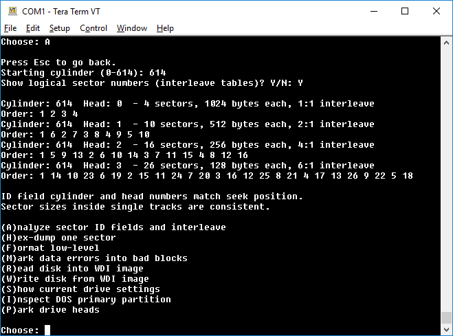
If the disk can be read, a track that shall be always readable is to be chosen (cylinder 0 head 0, for example). Run the Analyze option on it, to determine sector size and counts. Then, call Hex dump of 1 sector on that particular track, using the sector number and size from the Analyze results, and when Winchesterduino asks to read with verify, press Yes. If the data verify mode was chosen correctly, the result will be read OK; otherwise a data error will show up. Try a different mode then.
You can also use the hexdump option with the “Read with verify” set to No, in which case it will also dump the checksum bytes and the polynomial used, for a manual calculation. In all cases this option needs to be determined and set correctly, especially when writing disks. Otherwise, a mismatch can lead to data corruption – all sectors being marked “bad” by either Winchesterduino or system with the drive in it, even though they really aren’t “bad”…
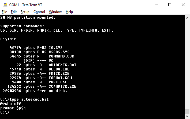 Simple “DOS shell” filesystem traversal, if the disk has a primary partition.
“TYPEINTO” creates new text files or appends text into existing ones.
Also, if the number of heads entered is less than 8, Winchesterduino will ask if the drive requires the “reduced write current” line, i.e. pin 2 being /RWC instead of /HDSEL. This only applies to real dinosaur drives such as the original ST-506 and ST-412, and is not to be confused with write precompensation, which adds delays to the write signal.
The option whether to use buffered or “ST-506 compatible” seeks is whether to send a fast pulse train to the drive to move the head in one cycle, or whether to wait a fixed time in-between steps, like when actuating a floppy drive head carriage. A buffered (fast) seek can be used unless the stepper/head actuator has seeking problems (use the Analyze command to determine), or the drive is a proper old ST-506/412.
The rest of the options are fairly self-explanatory. For example, drives with voice coil actuators (servo heads) auto-park in the center on powerdown, whereas those with stepper motors have a landing zone requirement where to seek the head, before attempting to relocate the drive.
All of these parameters are present in each drive’s technical specs – if it withstood the test of time, or has been scanned and put online 🙂
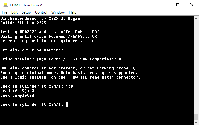 No WDC or data separator chip – running in minimal mode.
Drive select always on for the data output signal to be present.
Of course there are always some pitfalls and gotchas, even with a later WDC chip as the WD42C22 this project uses.
Ignoring the mechanical parameters and unreliability of these prehistoric drives; and apart from matching the data rate, data field CRC/ECC mode and how many checksum bytes to read or write; this setup only supports soft-sectored drives that have sector ID fields of exactly 7 bytes, always ending sector ID fields with CRC – as seen below. This should be compatible down to the original ST506/WD1010 mode, but it immediately rules out other non-standard sector formats, such as Winchester disks used in mainframe systems, etc. For those, whip out the ‘scope and the analyzer, because the WDC will not detect any other ID fields on disk. Writing such disks becomes an even bigger challenge.
In contrast (with MegaFDC for example), floppy disks were designed to be swappable between systems, at least to some extent. Not so much when it came to hard drives…
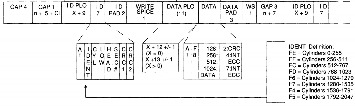 The soft-sector MFM/RLL track format of an ID and data field, required (and written) by the WDC
And then the speed bottleneck.
By default, a conservative bitrate of 115200 bps is used here between the AVR and the USB UART. Minus the overhead, this translates to a maximum practical data rate of around 8 KB/s; which is painfully slow by any standards. Although this might be tolerated for a floppy drive project, as floppies are inherently slow by design, imaging hard drives like these, – be it MFM with a grand total of 10s of megabytes capacity – it’s just as sluggish as it can be. Especially if whole sectors aren’t empty, or of the same byte value (Winchesterduino transmits just 2 bytes for those). This gets worse if the drive is formatted with large interleave, or has a lot of small sectors, bad blocks or R/W head issues.
Now, the problem with increasing the bitrate, is that the new value must be compatible with both the configuration of the AVR and the UART onboard. I have performed some experiments with my cheap Mega2560-clone board and its CH340G UART, and the fastest bitrate with no data transfer interruptions, with the Mega2560 clocked at default 16MHz, was observed to be 500000 bps.
This is a non-standard bitrate though, it is not officially supported by the CH340, and on Windows it requires a terminal application not “tied” to the standard rates of the Windows serial port driver. But it sure does reduce the image file transfer time in half!
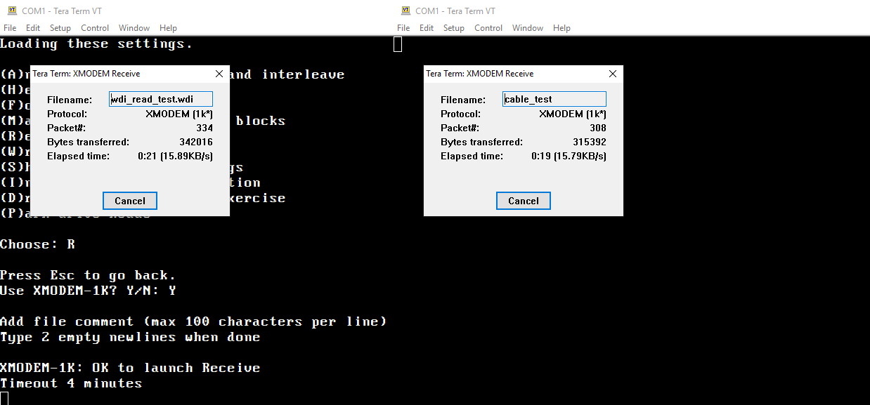 XMODEM with 1KB packets, running at 500000bps, on Winchesterduino doing disk reads (left), vs. null-modem file transfer between 2 physical computers (right).
It sure doesn’t make use of high bitrates effectively… Then again, it’d be a better option to save disk images to an SD card on hardware SPI – instead of implementing a better transfer protocol – the resulting file size during reads is unknown, until it has completed scanning the disk.
This would also free up serial output for progress or error indications.
Cool, great job!