I have once stumbled upon an interesting article from 2018 published on retrocmp.de, discussing about provisions on connecting an 8″ floppy disk drive to a PC. You know, those huge “boat anchors” that accept flexible disks just four inches shy of an LP record, in exchange of a couple of hundred kilobytes data storage. That sort of type. The experiment there was to connect that big ol’ mainframe-era drive to a normal PC, as to be used under DOS as an archival tool. In 2019, the author got mixed results from his experiments: he was able to fool the system BIOS, tricking the 8″ drive to work with a geometry that of a 5 1/4″ 1,2MB DS HD drive. For the rest, he’d use a proprietary controller card paired with some paid software.
As a follow-up to his article, I’ve decided to tinker around on how to have fun with these clunkin’ beasts using a classic PC equipped with a vanilla floppy-disk controller (FDC); without any commercial hardware, software, or some USB controlled thing-a-magic with Windows 10 support. Besides, 8 inch drives predate PCs as we know them, and classic floppy drives with PCs were mostly used during the DOS/Win9x decades. Behold!
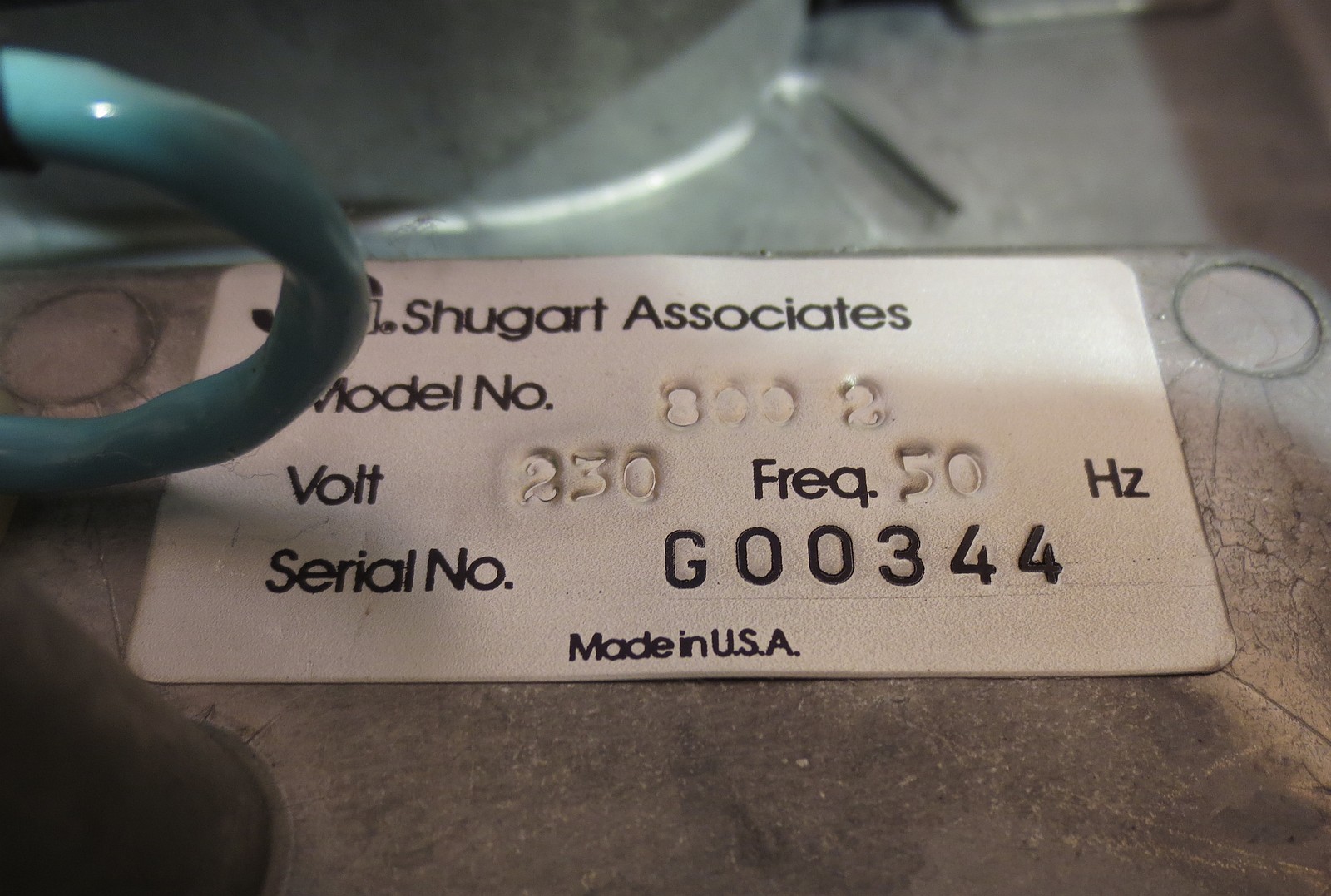
 From left to right: Shugart SA800-2,
CDC 9046 (Magnetic Peripherals BR8A8-A),
Czechoslovak Consul 7115,
and a size comparison of an 8 inch floppy with a pirate copy of Metallica 🙂
So here we have the three different 8 inch drives that I have experimented with: a classic, full-height single-sided Shugart 800, a full-height double-sided CDC BR8A8-A, both U.S. production, and a half-height, double-sided Consul 7115, this one made in Czechoslovakia. Despite all of them being different, they had at least something in common: all of them were over 40 years old and in an untested condition. Well, at least something 🙂
Jokes aside, all 3 of them have documentation available. This is very important – 8 inch drives are no plug-and-play, and with no proper schematics and docs, they are only good to use as door stops.
And, all of them address 77 tracks on a soft-sectored diskette. Hard-sector-only drives, or hard sectored floppies, won’t work here.
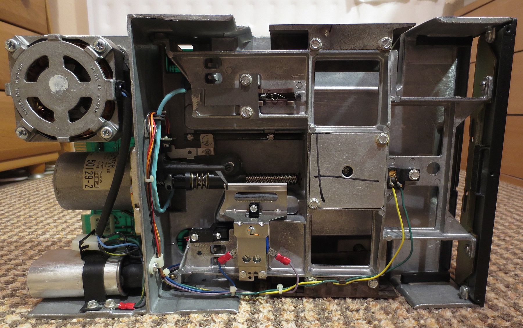

The Shugart SA800-2 in detail
Shugart drives were once considered the de-facto standard back in the 1970s. Since IBM originally invented the 8-inch diskette to store microcodes for their mainframes, Shugart Associates was one of the vendors that was producing the drives for them. Even the former PC floppy disk interface is sometimes called the (modified) Shugart interface; “modified” because of the READY line; but more on that later.
The above-pictured SA800 is a single-sided drive, and with a PC, it will read single-sided floppies ONLY. Double-sided 8 inch disks have an index cutout in a different location – a single-sided drive only has 1 photosensor, and since it is in a different location, it won’t generate the INDEX signal, on which the PC FDC is reliant – it will think there’s no disk in the drive.
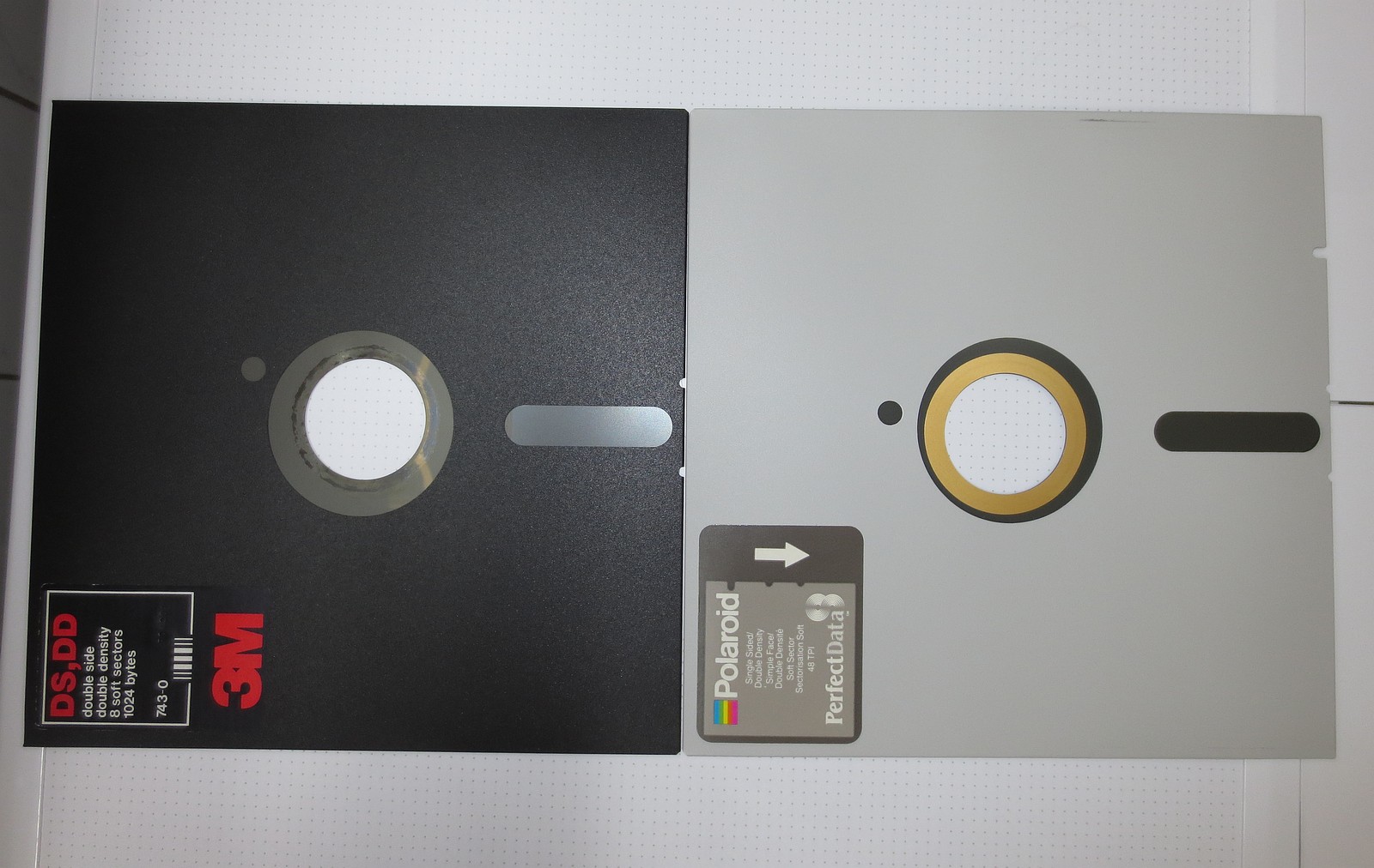 Double-sided (left) vs. single-sided (right) diskette
Notice the shifted index hole next to the center spindle.
Additionally, the SA800 drive of mine, was configured to be used in a TRS-80 Model II, i.e. with a non-standard termination and jumper settings. Luckily, the Shugart drives have manuals easily available online. As such, configuring the drive back to its factory settings was the only “electronic” necessity to prepare the drive for being used with a PC.
 SA800 termination and jumper settings for a Tandy TRS-80 Model 2
(ie: before restoring to factory defaults)
The Shugart and Shugart-compliant drives use a 50-pin card-edge bus connector. An adaptor can be made from a discarded ISA slot and a card-edge connector cut from a broken 5 1/4″ drive, to fit a common PC FDC cable, as I did.
You can also just cut the PC floppy cable and solder directly to the PCB of the drive. It might not look nice, but it works. In all cases though, the cable shall be cut as short as possible, and ideally away from the mains power wires (see below), in order to avoid all sorts of data errors.
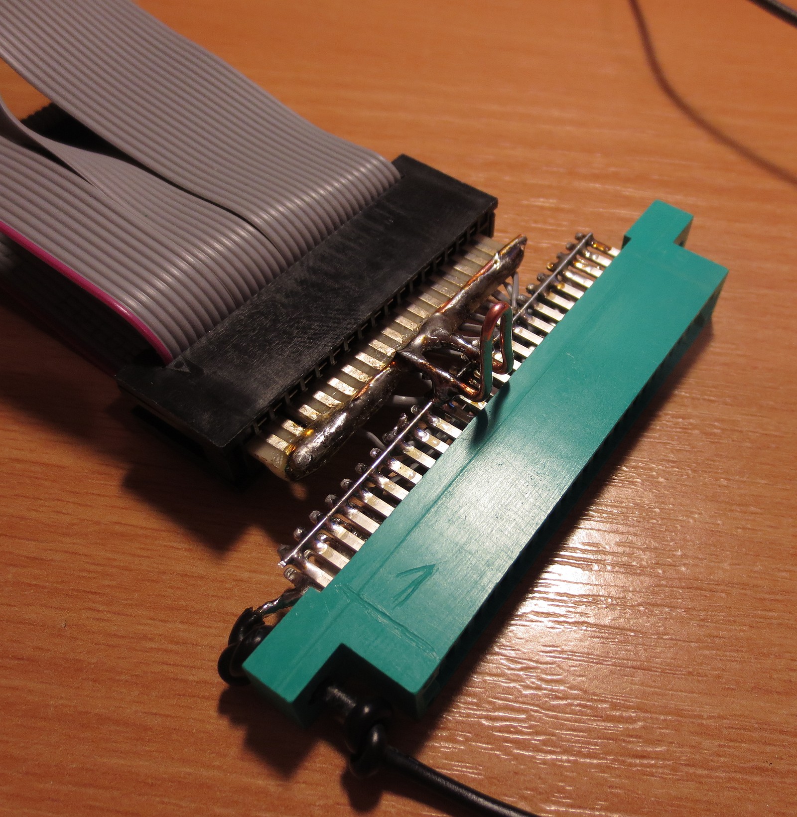 50-pin card-edge Shugart to 34-pin PC card-edge floppy connector adaptor
Can be used with Shugart and Shugart bus-compliant drives.
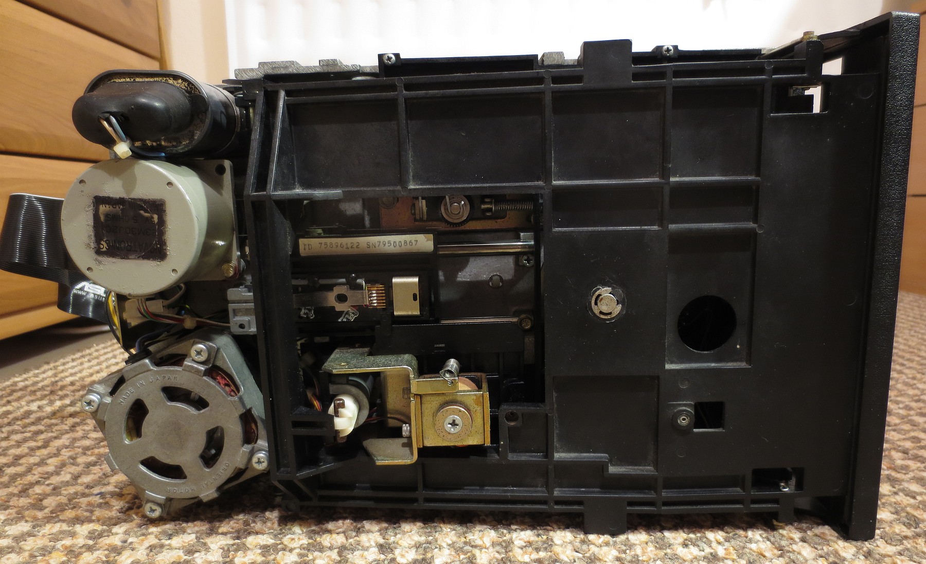


Magnetic Peripherals BR8A8-A, in detail
This CDC/MPi BR8A8-A drive was a tougher cookie to set up properly. The available manual did not list the drive’s part number 77618006 (ending with 006) in its Configuration table. Plus, these drives (CDC 9046-series) have a 50-pin IDC connector (i.e. like for a SCSI cable, not for a card-edge bus), with its pinout totally different to the Shugart pinout – take care!
From what I have found out to work, is the pinout for a third column in a table “J1 PIN CONFIGURATION AND ASSEMBLY USAGE”, page 5-4, page no. 38, of said document. This pinout on the IDC connector needs to be matched with the appropriate signal pins of a 34pin PC FDC – but more on pinouts below.
However, the drive was still not reading any disks at all. Despite the drive was INDEXing properly, a lack of differential analog signal between test points TP1-TP2 led to a faulty read amplifier MC1733CP. Thankfully I have managed to salvage a functional one – a UA733CN variant – from a circuit board of a Tandon TM-100 5,25″ floppy drive (the one used with an IBM PC). After desoldering, I have put the replacement in a DIL14 socket though.
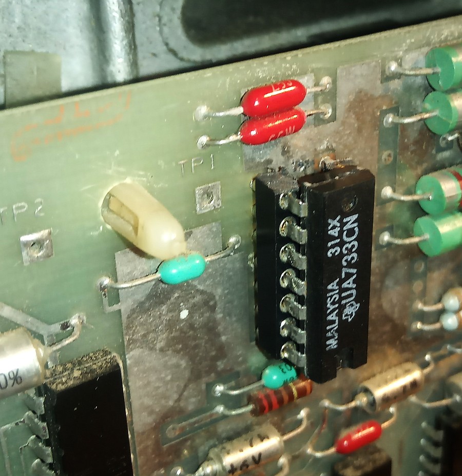 Replacement of a video amplifier chip used as a head read amplifier/pulse shaper and put in a socket. UA733CN/MC1733CP etc., can be used.
And since the bus connector of this drive is not compliant with the Shugart bus, I’ve just cut and soldered a 34-pin PC FDC cable behind the drive. After this, the drive sprang to life. Yay!
The drive also has 2 heads, which means it will read both single-sided and double-sided disks properly.
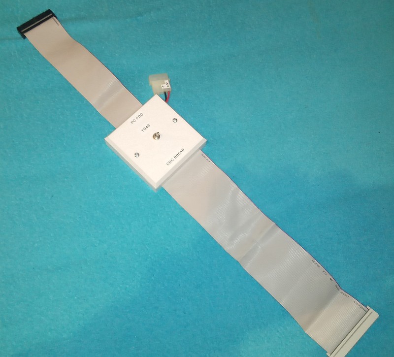 A makeshift adaptor between the FDC and the BR8A8-A.
A cut SCSI cable goes into the 50pin IDC connector of the drive, and a 34pin FDC to the PC.
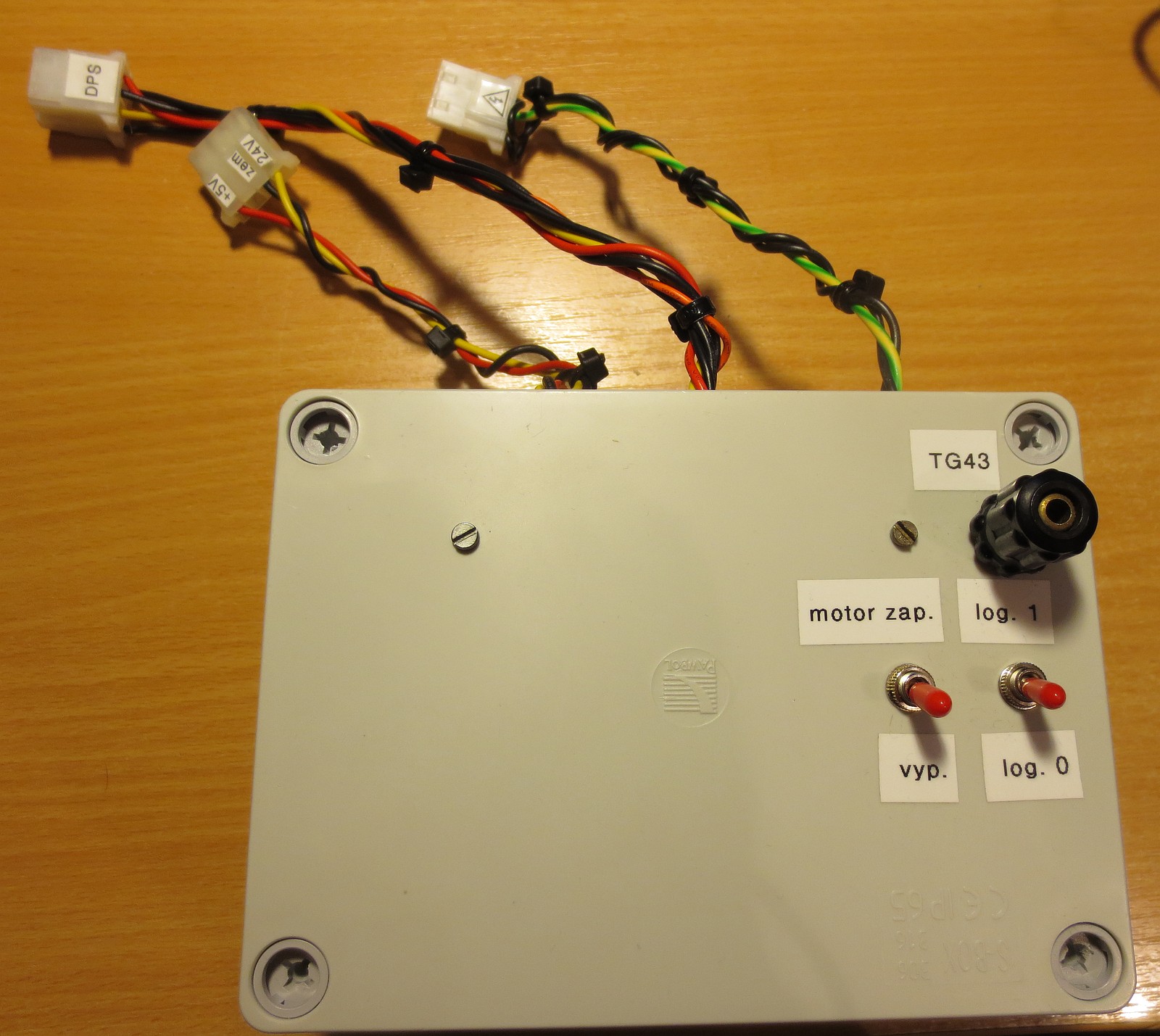
There’s also a switch and a 5 volt connector to handle the TG43 line, but more on that later.


And now comes the icing on the cake, the Consul 7115 from the Iron Curtain. This half-height, double-sided drive brought me the most troubles to get it running right, and eventually I gave up on it.
The drive had a Shugart-compliant bus, however the connector was not equally spaced from the sides, which I had to fix with some epoxy resin and sandpaper – unless I wanted the plug to short the bus by the contacts being off-set. And, the longer the drive ran, the more problems have surfaced: the write protect IR LED inside the photosensor went out, the DISK CHANGE logic disengaged both heads if the disk was changed and an attempt to read side 1 was selected; the MC3470 read amplifier gave up on me, due to faulty ceramics in the discriminator (filter), so the drive could write – but not read – its own disks, and then the write circuits failed too: every fourth track was written unreadable.
Ah well. At least I could make the thing sing 🙂
Consul 7115 “singing” Duke Nukem’s “Grabbag” theme song
Perhaps there were some top secret nuke codes on the floppy, too!
Okay. So – how would one actually connect these drives to a PC floppy disk controller? Well, you need the pinout of the 34-pin PC FDC, the proper setup and pinout of your drive (ideally, to be found in the technical documentation, a Shugart compatible pinout is available here), and – at bare minimum – a 34pin PC FDC cable, to be either cut and soldered, or to be made an adapter from. The odd pins are ground, the even ones are signals. You need to connect the grounds between signal wires that are in use, so that the signals do not cross-talk between each other – this is important.
On the PC connector side, you will need to make the “kludge”, the cable twist between pins 10 and 16. This is because you cannot properly combine an 8″ drive with a 5,25″ or a 3,5″, explained below, so it’s good practice to connect only drive A, and jumper/DIP switch the 8″ drive for drive select 0 (DS0).
The signals that you will need to match from the FDC to the drive, are Index, Motor Enable/Head Load, Drive Select, Head Select (on double-sided drives), Direction, Step, Read Data, Write Data, Write Gate/Write Enable, Track 00 and optionally, Write Protect.
On the PC FDC side, connect the Disk Change directly to Ground, for “drive always ready” (or else you will get “not ready” errors). Do not use or connect the Ready signal on the 8″ drive side, the PC FDC does not care about that. This is why the 34pin PC FDC is called as a “modified” Shugart bus – the PC FDC expects a “disk changed/NOT ready” instead of a “ready” signal.
Please note that if you do plan on setting the 8″ drive as a fake 5,25″ 1.2MB drive in BIOS, you need an 8″ drive that already provides a valid Disk Change signal – and connecting this signal to the Disk Change line of the PC FDC, instead of tying it to GND as instructed above. This is because the BIOS will check the changeline for all configured drives except when set as “Not Installed” or “5,25 360K” – and failure of providing a proper Disk Change signal (i.e.: HIGH when the disk is changed, falling automatically to LOW after seeking the head), will yield Not Ready errors!
On the 8″ drive side, inspect if it has a TG43 line on the bus. If yes, you need to pull this line HIGH (e.g. through a 1k resistor to +5 volts) if the head carrier goes past track 42, and pull it DOWN (to GND) if the head carrier is between tracks 0 and 42. If there’s no such signal on the bus connector, the drive does this automatically for you, usually through a phototransistor positioned on the head carrier.
With TG43 on logical 1, the drive reduces write current past track 42. You can think of it as a decrease in modulation (“volume”) towards the center when vinyl records are mastered 🙂 to prevent inner groove distortion, as the groove length gets shorter on same rotational speed; same thing with magnetic tracks.
If the drive requires TG43, but you only use the drive to read from disks, you do not need to connect this line. Then again, you can leave it permanently HIGH or LOW and don’t care during writing (and sometimes you cannot – especially during random access writes, i.e. not sequential image writes, you would have to flick that line high and low like mad). However, this can yield floppies that might not be readable on same drive, or on other drives. Or, get a drive that does not require this signal to be set manually.
If you decide to connect the Write Protect line, take care – the write protect notch works exactly the opposite way compared to 5,25″ disks. Here, if there’s a notch punched onto the top of the disk, it is write protected, and you will need to use masking tape over it to make it writable. And, if there’s no such notch, and you want to make it write protected, then you need to punch it 🙂
 The makeshift power supply for all 3 drives.
Contains 3 small switched SMPSs: +24V, +5V and -5V (a floating +5V supply connected in reverse).
You also need to provide mains AC for the electric motor of full-height drives, and the control of the TG43 line for drives that need it.
Okay, so the drive is jumpered right, the data cable is ready, but what about power requirements? Here, the technical docs of said drive, come handy again.
Usually, an 8-inch drive requires at least two power sources: +24V and +5V, both around 1.5A (check the manual). An early, non-LSI Shugart SA800 also requires -5V. And, if it is a big ol’ full height drive, also mains AC for the synchronous motor driving the spindle. In that case, both the voltage and frequency of the mains must correspond the sticker of the drive, although, some drives allow 50/60Hz switching by rotating the drive pulley (CDC BR8A8-A), otherwise, the floppy might not be readable on other drives. Or at all, for that matter.
Half-height 8-inch drives usually source their spindle motor from the 24V supply, and won’t require mains AC with proper frequency and voltage. In both drive height types though, 24 volts is used to drive the head load solenoid (electromagnet). Some drives often employ a 12V series regulator for the rest of the electronics except TTL logic, i.e. write transistors etc.
Compared with 5,25″ or 3,5″ drives, the spindle motor in 8″ drives is “always on”, and the “motor enable” FDC line is actually connected to the “head load” input of the 8″ drive, actuating the head load solenoid. However, in full height AC-motor driven spindles, it’s a good practice to provide some forced-air cooling of the motor, or switch it off manually with an AC power switch when not in use, as these motors usually get quite warm when operating. /And, depending on the status of the motor bearings or lubrication, quite loud, too. A friend of mine had a CDC drive with the spindle sound akin to that of a free-spinning table saw./
The makeshift power supply pictured above, employs two AMP connectors (glued together and keyed) with 24V, +5V and -5V to connect to a Shugart drive, one AMP connector for the mains AC and a classic modified Molex power connector to connect to the rest of the drives, Consul and CDC, providing +5V and +24V. For the CDC drive, there’s a banana jack for the TG43 line, connecting it either to GND or +5V through a 1K resistor.
A corresponding Molex hangs out of both CDC BR8A8 and the Consul drive, the latter from a prominent orange-color screw terminal 🙂 These were proprietary connectors, I didn’t care.
 Experimental connection with an IBM PC, using the 37-pin D-Sub connector from the rear.
This does not work properly – 8″ drives require high density capable controllers.
And now comes the fun part! There’s a great distinction of what follows afterwards, depending on how you want to experiment with the drive on a PC.
- If you want to have fun with the 8″ drive directly under DOS etc., a classic high density capable FDC is all what is required. High density capable means an ability to read and write regular 1,44MB floppies.
For this purpose, instead of “faking” the 8″ drive into a 5 1/4″ geometry through BIOS (which won’t work properly anyway), check out 8FORMAT! - But, to be able to archive and/or write original 8″ disks (CP/M, mainframe stuff etc) into image files, and vice versa, you WILL NEED a floppy controller that supports FM data transfer, with 128 bytes per sector, USING the 500kbps “high density” transfer rate. In other words, an FDC, which is both FM and HD-capable.
For this purpose, a utility such as Dave Dunfield’s ImageDisk (IMD) is preferred. This allows you to grab the disk into an image file, and then take it out for analyzing, or into an emulator/reader application that can read custom non-PC formats, make changes and write it back to the 8″ disk using IMD, if necessary.
To determine, if your controller is FM capable, use the TESTFDC tool from ImageDisk, or find your controller chip in this table to see the results. Or, 8FORMAT can also be set out to format single-density FM disks and will give errors if the floppy controller does not support such an operation.
Historically, 8″ diskettes were either single- or double sided, and single-density (SD), versus double-density (DD). In both cases, the transfer rate (between the CPU and the FDC) had been 500 kbps. However, the former type employed a geometry of 26 sectors per track, 128 byte each, which – when written with FM encoding, with 2 bits per each data bit (one clock bit reserved) – it yielded a practical data rate of 250kbps at a transfer rate of 500kbps.
26 128-byte sectors resulted in 250K of unformatted disk capacity per side. That is, 250K for SS/SD 8″ disks, or 500K for DS/SD 8″ disks.
Double-density 8″ media could be formatted with 26 256-byte sectors, or 8 sectors with 1 kilobyte each, with a data rate of 500kbps MFM (at a 500kHz clock rate, 1 bit per 1 data bit encoded; data rate same as 1.44/1.2MB floppies). With this geometry, 1.2MB for DS/DD 8″ disks could be obtained.
Although there were 8086-based personal computers, such as the Seattle SCP equipped with 8″ Tarbell controllers running MS-DOS 2.11, IBM PCs and their descendants that we know today, on the other hand, never supported 8″ floppies. And, for both 5,25″ or 3,5″, only a physical sector size of 512 bytes with MFM modulation, was supported… Well, almost. 8FORMAT can tweak that. 🙂
Side note: MS-DOS versions 3 to 5 claimed “support” for 8-inch drives through DRIVPARM or DRIVER.SYS with an /F command-line switch, /F:3 for single-sided and /F:4 for double-sided drives. Don’t bother, this doesn’t do anything at all.
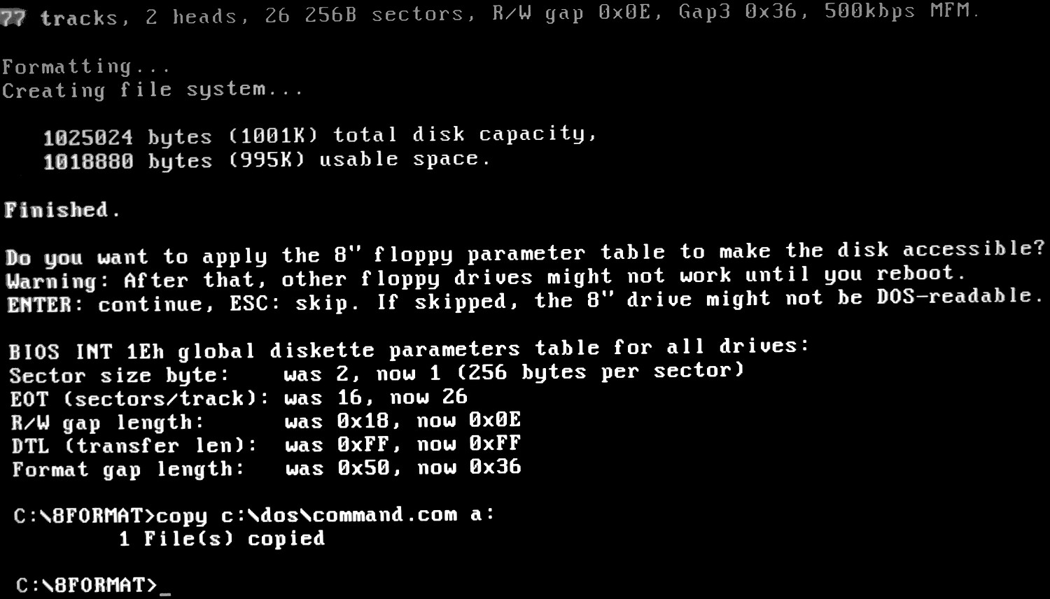 Experimenting with a 26-sector, 256-byte 8″ floppy under DOS with 8FORMAT
Shugart SA-860-1 is working fine with my PC. Even Windows 7 can talk to it. I do use 8FORMAT in a DOS boot, then format for /t:77 /n:15 and it’s happy as a clam. (Can’t format directly in Windows 7 with those parameters, but…) You CAN also access directly in LINUX with the FDUTILS package…
Glad to hear! Unfortunately I didn’t have a machine that could reliably run Windows 7 and have a floppy disk controller on the mainboard at the same time 🙂
My CDC /Oklahoma Data/ was not fully compatible with the 1,44MB drive stepper timings, and the Shugart I have is a single sided drive only.
If you use 8FORMAT with type EXT1, the /N: can be used with 16, and with type “CRAM” (undocumented), even /N:17. Whereas, the platforms I ran 8FORMAT on, were too old to run any sensible kind of a Linux distro 🙂
Which kind of floppy disk controller do you use?Can you give me its driver files?
I want to try on my PC.
use automatic write current limiter ))
https://zx-pk.ru/threads/33316-ogranichitel-toka-zapisi-8-dyujmovogo-diskovoda.html
Yes, that can work. Or a small photoswitch hooked up to one of the flip-flops of the TTL board, i.e. past 43 – ON, again past 43 – OFF and so on.
When the interface signal is activated to a logical zero level, the lower value of the write current is s’9lected
for writing on tracks 43 through 76.
I well remember using my Imsai 8080 with dual 8″ floppies and a paper-tape reader. I still have it and as of about 2 years ago it still works, and I’ll likely never get rid of it, either. Thank you for this trip down memory lane.
Even though the article is historically inappropriate, as in – interfacing a dinosaur drive using later caveman technology – I’m glad you like! You might aswell try dumping the old floppies to binary images with the above approach, and take sneak peeks with hexeditors and whatnot. That feel must be like digging out a time capsule…
From the 8″ disks I tried to read on my own, most of them contained a hacked-up version of CP/M running on Iron Curtain equipment; dBASE cardfiles of personnel and the like…